Redesign.IT – Spinfire Flame Bearing and Bearing Housing

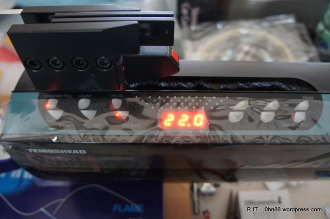
Back in June 2013, I bought a new racquet stringing machine. It was a Spinfire Flame with a Wise 2086 Electronic Tension Head. It happened to have a special price on it, so eventually cost me $1250 at the time.  These are still being sold now albeit at a slightly higher price – $1799.

https://www.tenniswarehouse.com.au/spinfire-flame-with-wise-tension-head.html

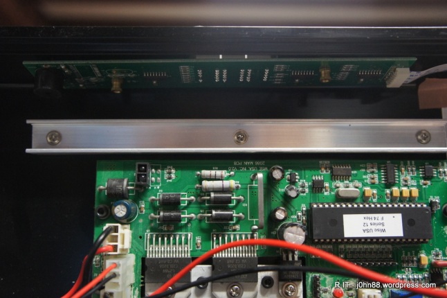
When I had received it, and was using it for the first time, I noticed that the turntable wasn’t spinning very well. Actually, it was a little notchy, in that it would turn but seem to settle in certain positions. I didn’t worry about it at the time as I had a few badminton racquets to string, but several weeks later, I decided to investigate the problem. I found that one of the bearing races was cracked.

I checked and found a local supplier, ABC Bearings, that had this in stock and got a price. I also notified Tennis Warehouse in Melbourne about the problem, and they were happy to reimburse me for the cost of the bearing – since that was easier than getting a bearing and sending it to me.

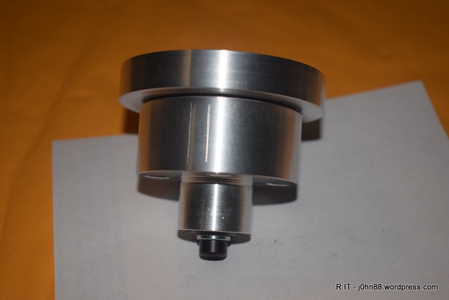
I replaced the bearing and found that it had to be done up very tight in order for the turntable not to feel sloppy. The design of this bearing housing was two bearings kept together with a 8mm diameter bolt.  Here is a photo of the bearing mount, upside down showing the relative positions of the parts. I had made a plastic sleeve for the bolt some time ago, to make improvements to reduce the sloppy fit.

DSC_1954

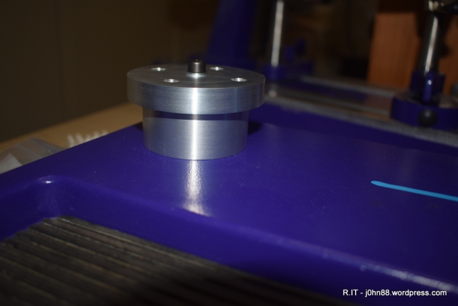
Sometime later, I also made a spacer to raise the turntable a bit higher. The photo below shows what it looks like when assembled and with the spacer that I had made.

DSC_1956

This housing is mounted to the base, and the turntable sits on top. Tennis racquets can be strung at up to 60lbs, so there is considerable side force on this housing, and to stop the turntable from tipping or showing considerable slop, the bolt has to be tightened so much, that the bearing can break.

Fast forward many years to about six months ago – I was thinking about how I would redesign this housing. I looked up stub axle designs, like trailer wheel mounts – but nothing appeared to be easy to make with my lathe and milling machine. So I decided to design it from scratch, knowing what sort of loads I would need to handle.

Instead of the existing ball bearings which are compression types, I went for ball roller bearings that would handle the side loads better than the original. Also the axle would be minimum 12mm, not 8mm – so would be stronger. Another larger bearing for the top, then a needle roller bearing to allow the turntable to spin easily even when tightened.

Then ordering the bearings, and working out how to machine the parts out of aluminium, and the axle out of mild steel – it was time to make a prototype. I did have photos of the machining process, but won’t bore you with them here.

DSC_1960

My design is shown here with the top part removed, showing the axle with the slight taper. The needle roller bearing is visible in the bottom housing to handle the vertical load, then the other bearing with the rubber seal.

DSC_1958

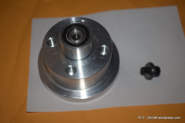
Here you see the assembly shown upside down with the smaller bearing, then the tensioning screw to the side. Unfortunately, when I had this bottom piece in and out of the lathe, it sort of dropped onto the concrete floor, so it shows some slight dents and marring on the edges – only cosmetic though.

DSC_1957

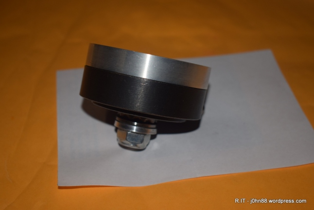
This is the completed assembly – with some slight markings on the surfaces due putting it in and out of the lathe. The earlier photos showed that the bottom piece had four tapped holes. There are also four tapped holes in the top piece that the turntable is screwed onto.

DSC_1961

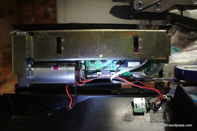
Finally a look at where this goes when mounted to the stringing machine base with four bolts underneath. My design was to be a drop-in replacement, i.e. remove the old bearing assembly, and drop mine in place and screw it together. Well almost! I had to use bolts of slightly different length. The only thing I am missing is the locking screw that locks it from rotating – but that is a feature that is only used for a couple of special tennis racquets, and I don’t anticipate having to string any of those ever.

Does it work, you ask? Yes, actually the turntable turns very freely now – although I can hear the roller bearing noise and with none of the original slop that could be felt.

Repair.IT – Wise 2086 Professional Electronic Tension Head

Occasionally, in the electronic repair world – we may be unable to obtain replacement parts. In a situation like this, we then have to resort to replacing the module that has failed, either with modules from the manufacturer or modules that have a similar function.

This is about my Wise 2086 Professional Electronic Tension Head – which is mounted on my Spinfire Flame Stringing Machine. The tension head allows the string to be gripped, then pulled linearly until the required tension is reached – then, if constant pull is enabled, it will continue to keep that tension. A couple of weeks ago, I noticed that one of the segments on the second LED display didn’t light up. For those who know about 7 segment LED displays, it was the B segment. Sometimes like today, on powerup – it will be working.

SONY DSC

Wise 2086 Tension Head – display working

But then later on, the B segment will stop.

SONY DSC

Wise 2086 Tension Head – display not working properly

A couple of weeks ago, I emailed an enquiry to the supplier in Melbourne, Tennis Warehouse – from where I purchased this stringing machine about three years ago. I asked about any problems if I open up the tension head and mentioned the display problem. I had heard on the internet that occasionally, opening up the tension head would give an error on next powerup, that would require some procedure to be followed. I received a quick response that this will not happen, and that the screws are different lengths – something to watch out for when I open the case. Also that the display board is available for $45.

Just a week ago, on Friday, once I had finished stringing a few racquets – I opened up the case, then had to remove the main carriage to get to the display board. I removed the board and checked the part number of the LED display. It was a HS-3101AS – which is a 0.3 inch display but in a larger housing with 10 pins. I checked my usual supplier – element14, to no avail – this part didn’t appear to be available and I was unable to find an equivalent. A search on the internet also gave me a possible equivalent – HS-3101AX, but this also didn’t help.

I could find other similar size displays but when I check the pin connections, those are in two columns of five pins, 5 mm between columns, but mine are 7.62mm between columns. I could find it on alibaba, except that they only indicate it as being an integrated circuit will no actual photograph – so I was hesitant at ordering something, sight unseen. I decided then, to bite the bullet and order a replacement display board. I had to email a photo of the display board so that they could confirm the correct replacement. Then on Thursday – my replacement board arrived.

SONY DSC

Display board for Wise 2086

SONY DSC

Display board for Wise 2086

The top on is the original, version 3.1 and the replacement is at the bottom – version 3.3. Some slight differences – the main thing being that the speaker was moved, making it much easier to install the board.

SONY DSC

Wise 2086 Tension Head

Here is a photo of the board installed – at the top. Previously the speaker would get in the way of my fingers when trying to remove and install the small brass nut.

SONY DSC

Wise 2086 Tension Head

Then a photo with the carriage mounted back on.

Next thing to do is to work on one of the base clamps on the stringing machine – which had been causing problems that it would unlock, when I didn’t want it to. Tennis Warehouse sent me a replacement base clamp at the same time as the display board which was very good of them.

The motto of the story is that you cannot always replace component parts – in fact, not many companies will do this, even for manufacturers – they usually replace the module. Sometimes, if the modules are valuable – they are returned to the factory for refurbishment – which usually means replacing the faulty components, but not always. The common factory refurbished cameras and whitegoods – are usually just repaired with replacement modules – often happens with goods that are dead on arrival, they go back – repaired by swapping modules, then comes back out as factory refurbished at a very good price and with warranty, generally.

Relocate.IT – Spinfire Blaze stringing machine turntable base end posts

Last Friday evening, a friend brought over the turntable base from his recently acquired Spinfire Blaze stringing machine.  This stringing machine has fixed end posts that allow for mounting a tennis racquet with the side supports in the appropriate place.  The problem is that my friend only strings badminton racquets which are smaller in size than tennis racquets.  The badminton racquet can be mounted but then the four side supports are only supporting the racquet near the ends instead of near the middle as they should be.

After some taking of measurements with a badminton racquet mounted and a bit of scratching heads, it was determined that we need to move the end posts closer by 5-6 cm. The end posts are fastened by M6 bolts – with a four hole pattern that we saw is separated by about 2.5cm.  Suddenly we had the light globe event – a bright idea, how about we mount the end posts by using only the two closer screw holes, which should move the posts together by 5cm.  We did this and sure enough – the badminton racquet could now be mounted with good support on the sides – sufficiently close enough that now we could be confident of stringing these badminton racquets without worrying about the racquet head turning circular or breaking.  Since it was getting late, we would leave this until I have some time during the day.

Today was the day to “relocate.IT” the end posts, that is. I stuck some stickers on the base where I expected the new hole to be, then measured across by 25mm and marked the centre of the hole.  But when I look down the base, it appeared that the centres were not quite right.  I had another bright idea, I could just drill a template – which is what I did.  I got some scrap aluminium flats, and drilled three holes each 25mm apart.  I could do this on my milling machine, because the X axis has a dial that has incremental marks every 0.02mm.  Of course, a full rotation was 1.5mm, so a matter of a bit of maths or just counting the rotations, to get the 25mm required.  Two holes were drilled at 6.5mm then the third hole was drilled at 3.3mm.  I have an automatic centre punch which has a tip about 3.2mm in diameter, so by lining up the two existing holes on the turntable base, I could punch the centre of the third hole – the one I need to drill.  After doing this, I could see that the punch put the centre where it should be, and a bit different from my original markings.

SONY DSC

Here is a picture of the base with the two holes punched, the template and the automatic centre punch. Now to mount it on my little milling machine.

SONY DSC

Here I have it mounted, and a center drill in the drill chuck – the center drill is used to start the hole, and allows me to adjust the X-Y table to properly center the marking, then drill it. The base is aluminium, so after drilling the center hole, I went straight to the 6.5mm drill. If this was a steel base, it is better to use an intermediate drill like 3.5mm before the 6.5mm drill.

SONY DSC

After drilling both holes, it was time to swap the ends around and do the other two holes. Then use a countersink tool to clean up the edges of the hole so that it does not have sharp edges, then to reassemble the end posts.  My friend also invested in automatic base clamps, so I installed the base clamps before I installed the end posts.  The end posts have one control to move each pair of side supports in and out, so after mounting the end posts, I also had to mount an actual racquet, then adjust the end posts so that the side supports with clamp the racquet at the same point.  Only a minor adjustment was required, then retighten the end posts.

SONY DSC

And now here is the final product sitting on my tile floor.  The result is that the posts have been moved 2.5cm towards the centre on both ends.  Now my friend can use this machine to string badminton racquets.

Repair.IT – Advance Combo 3800 stringing machine tension head

In July last year, the local Eagnas importer had referred an inquiry to me.  A man in Melbourne had a problem with his stringing machine.  The machine is a Combo 3800 which is also sold by Eagnas as well as other companies.  Anyway, the problem is that the machine reports a load cell cable error – which is a generic error that the readings from the load cell are out of range.

photo 2

The man sent this photo to me of what it displays when he does the +10 power on test.  I.e. press and hold the +10 button down, then power on.  It shows 99 – bad, which in my opinion very likely means that a transistor had failed causing the ADC to also fail.  I told him the location of the transistor and ADC.  He said that he had a friend who might be able to do the replacement for him and we left it at that.

Ok, around the end of January I was going through some old emails and I came across his, and wondered what had happened, so I asked him.  It seems that he didn’t get anywhere with it other than getting the transistor and replacing it.  Still the same error – so I said that the ADC replacement should fix it.  Eventually after a few emails back and forth, he decided that it might be best to send it up to me, which in due course he did, arrived last Friday week.  On that weekend, I had a look at it, found a broken wire, fixed that and after some measurement of signals concluded that the ADC had actually failed.  The ADC was out of stock at the supplier, but it eventually arrived on Friday – all the way from Singapore.

On Sunday morning, I woke up a little early and thought that while everyone is asleep, that might be a good time to tackle the ADC replacement.  The ADC is that flat chip next to the big chip.  That flat chip is a 22 lead SOIC.  The length of that chip is about the thickness of my little finger.

SONY DSC

I use Chip Quik to help in removing these surface mount chips.  The Chip Quik is a low temperature alloy that mixed with the existing solder.  I put some flux onto the chip pins, then melt the Chip Quik onto the pins and go around a couple of times, then just lift the chip off the board.  Takes only seconds!  Then clean up the old solder and alloy with solder wick.  Then clean with isopropyl alcohol wipes, add flux again – drop the new chip in place and ready to solder.  To solder, I just need to tack on a couple of the pins on each corner – to stop it from moving around.  Then add solder onto my iron and just wipe the iron tip across the pins.  Do this a couple of times until each pin is wetted.  Do the same for the other side.  If any pins are bridged, just wipe the iron on the pins away from the chip.  All done – ok not quite.  I do this with the board removed from the machine, I had to then reassemble it into the machine which was a bit of a job because I find out that the board supports don’t line up with the mounting holes. No wonder the original supports were all loose, they had to be loose in order to fit.

Anyway, power on, the load cell error is now gone.  Go into the +10 power on test mode, and adjust for the appropriate value – should be from 34 to 39, not 99.  Great – next step, mount it on my test bench and try a low tension.  Not good – when pulling at 20 lbs, I get 13 lbs actual tension, try 40 lbs – only get 26 lbs.  Ok, I need to know whether or not the guy does tennis or badminton or both, so sent him an email.

He replied that he does tennis primarily.  Ok, so today I started to perform an adjustment at 50 lbs, which is adjust VR2 to increase the tension, until it is almost right, then check the reading in test mode is from 34-39, if not – adjust VR1, which affects the VR2 setting.  After doing a few iterations of this, I get it so that 50 lbs is actually pulling at 50lbs, and when I check at 20 lbs, I am getting 20 lbs – fantastic.  At 65 lbs, it is also pulling 65 lbs. Tennis is usually from around 45 to 70 lbs, so job is done – I packed it up and it is ready to go back down to Melbourne.

If you are looking for relatively inexpensive couriers and are not transporting glass, I would suggest e-go.com.au – I got a quote to send this 10kg parcel down to Melbourne – it would cost $11.22 if I take it to the Parramatta depot.  You can save 15% by sending depot-to-door, as opposed to door-to-door.  Door-to-door is less convenient as you have to wait around for the courier to come and pick up the parcel.  Since I go to Parramatta a few times a week, it is easy to take it to the Postnet shop which is the local depot for e-go.

One final photo – the failed ADC chip.

SONY DSC

Repair.IT – Eagnas stringing machine tension head with LED display

Just over a week ago, I was asked to look at a couple of Eagnas electric stringing machine tension heads.  These are similar to the Hawk 126e with LED display.  One tension head was pulling much too high in tension, the other just broke my string because it didn’t stop pulling, and almost pulled my electronic calibrator apart – I remember seeing the display go up to 95 before the string snapped.  I was only testing it at 20lbs.  Note to myself, next time – use badminton string so it should snap a lot earlier without going to such high tensions.

Ok, this machine that didn’t stop pulling – I took it apart – it wasn’t easy.  I eventually worked out that it is best to remove the 240/120V selection switch first – there are two screws under the label.  Then coax the front switch out through the front panel, and remove the six plugged in wires – after noting down which wire goes where.  Also remove the push button switch out the front but leave it loose.  After removing the four bolts that hold the cover in place, it was now possible to lift the cover and essentially manouver it off. Then reconnect the front switch to the correct wires.

After doing all of this, I then found out why the machine would not stop.  When the motor runs and pulls hard enough, a long lever should push onto a microswitch that will then stop the motor.  The part that was supposed to press onto the switch lever didn’t because the lever had bent away from it.  I bent the switch lever back so that it would activate.  Then I wanted to stop it happening again – so I made a little piece of wood, that would fit under the switch mounting that would stop the switch lever from moving sideways.  It will still move sideways, but not enough that it won’t be pressed when the right tension is reached.

SONY DSC

Next step was to check the tension that it pulls at.  To adjust the tension, I need to adjust these small trimmer potentiometers, the ones in blue.

SONY DSC

I mounted the tension head onto my test bench and proceeded to adjust and set the tension at 55lbs.  This machine would be used for tennis.  If it was for badminton, I would adjust it for 25lbs.  Once this was done, I put it all back together and then did a final calibration check.  This is by setting the tension at 20lbs then pulling and recording the tension that was reached, then increasing by 5lbs, etc until I get to 65lbs.  I can’t go any higher with my test bench because the tension calibrator support was starting to bend.  I will add another piece of steel to stiffen it for future testing.  Finally a photo of my test bench with it tensioning at 50lbs and a slight cluttered working area – lots of xbox controllers.

SONY DSC

[Note]  By measuring the tension at various points, we can plot this onto a chart so that we can determine what setting we need to get a particular tension.  This is what calibration usually refers to.