My journey of repairing and recycling anything I put my hands on that I believe is still useful. Not just hardware, but including software with relevant content and issues in the field of Cyber Security, Vulnerability Scanning and Penetration Testing.
I bought this wardrobe some years ago, and it had been used in my study room to store frequently used clothing, plus to put various boxes, cameras on top. It was originally placed next to the doorway. A few years later, it was moved to near the window as I had shifted my desk to be near the door.
Now, a few years – as my work progressed, I was having to walk back and forth to the sunroom where most of the work computers were set up. I create SOE images for Intel NUC’s used in the stores. I decided that it would be more efficient if I had the work area in my study, so there is less walking around and I can monitor the progress of builds more efficiently.
This meant that the Ikea Brusali wardrobe had to be moved. We moved it to the main bedroom where it can be a spare wardrobe. I noticed during the move that the back of the wardrobe had been separating.
You can see that the backing panel is held in place by flat headed nails, but over time and maybe moisture, the backing warps until the nails don’t hold it in place properly.
I decided that I could remove whatever nails were there, and I could use some small pieces of masonite. A few days ago, I cut some small squares of masonite material then drilled a 2mm hole in each. I then hammered the nails back in, through the masonite squares so that there is more surface area to hold the backing panels in place.
There were a few nails that were still holding in place – which I left alone. In hindsight, it may have been best to do this from the very beginning since those nails are not likely to hold the panels by themselves for a long time.
Anyway, another successful Repair.IT which isn’t related to electronics or computers or technology.
My son drives my old Honda Civic, a 1998 model sedan which has been running reasonably well for a long time, albeit with occasional issues. He brought the car over late Thursday night, apparently had a flat tyre while at Silverwater, and didn’t swap over to the spare wheel. Then, the next morning, I went to have a look at it, and the tyre was completely flat, and the bead had separated from the rim.
I took out the space saver spare wheel and the car jack and proceeded to remove the flat tyre and swap over to the space saver. Then drove to Bob Jane T-Mart to get the flat repaired. It wasn’t repairable, so got a replacement Razer branded one for $89. I would have preferred Michelin XM2 or Yokohama ES32 but they didn’t have stock and would have to order it in. The Razer should be fine as it is the rear driver side and the Civic is front wheel drive.
Swapping the space saver out and putting the new tyre in, took just over 4 minutes, but then I realized that the wheel cover goes on before the wheel nuts, so had to take the nuts off and put them back on again. The car is getting old anyway, and needs replacing very soon. Anyway, he went shopping and came back and said that there was something wrong with the car.
It seems that the brake lights stay on, even when the car is turned off. He brought the car back over, and I had a quick look and couldn’t find the brake light switch. I did see some small pieces of plastic on the floor. After a bit of Google, I found someone who had a short video on fixing this problem. After viewing the video, I went back to the car and managed to see where the switch was. There is supposed to be a little plastic stopper pad that pushes against the switch when the brake is released. This pad has disintegrated, and was in five pieces which explained what I saw earlier. I managed to push one large end piece back into the hole and it turned off the brake lights, but it would need replacing.
The part I needed is a 46505-SA5-000 known as a brake or clutch pedal stop pad. I couldn’t find any local place that had this part, and could only find it at online stores. I could find a picture of it, and thought that I should be able to make it out of nylon or something similar. I had the bits left over, and found that it was about 16-17mm in diameter and 4 mm thick for the pad, but there is a piece that jams into the hole in the brake pedal – which seemed to be just over 8 mm. After having the Civic brought back over, I measured the hole in the pedal and got about 8.1 mm. Also the piece that I had jammed into the hole had already broken into two – must have been brittle with age.
After rummaging around in my tool boxes, I found a large piece of 16 mm thick nylon or maybe polyethylene. I cut a square piece off and proceeded to turn it in the lathe, into a round cylinder of about 17mm diameter, then about 4mm from one end, turned it down to 8.25 mm overall, but then turned a small section close to the pad, down to 8.1mm. Presumably, it should press into the hole in the brake pedal which would then lock it in place.
I must have measured the hole a bit on the low side as the pad now is a slight loose fit, but it won’t come off and should be fine for a few years at least. In the above photo, the pad I made is the white piece that is pushing against the switch. When the brake pedal is pushed, the pad moves away from the switch that then turns the brake lights on. Whent he brake pedal is released, the pad will push the plunger back into the switch, thereby turning off the brake lights. Without this pad, the switch plunger doesn’t get pushed in and stays out, hence the brake lights stay on.
In my previous article on this Logitech Z320 – https://j0hn88.wordpress.com/2022/08/12/repair-it-logitech-z320-speaker-set-part-1/ , I mentioned that I had needed a longer screwdriver to undo two of the screws. Eventually, after a trip to Bunnings, and remembering that I needed a screwdriver, I did get it. After removing those two screws, the front panel would still not come out – it was getting caught near the bottom and side. I had to use screwdrivers to pry it open and jam something in to allow the 3.5mm socket to clear the housing, and eventually came apart. I found that there were two strong latches on the bottom of the front panel that lock the front panel to the housing.
Another view of the locking tabs – mean little hooks.
Once the front panel was loose, I could see that there were three cables plugged into connectors. One is for incoming power, another to connect the other speaker then the incoming stereo signal. I removed those cables to have a better look at the circuitry. I could see that it was using a TDA1517 2 x 6 Watt Stereo Power Amplifier Integrated Circuit. Then I plugged the connectors back on, switched on the power adapter for it and fed it from the Line-Out from my Sony Mini-disc player.
To my surprise, I could hear sound from both speakers. Maybe the speaker connector had a bad contact and by removing it and plugging it in again, that fixed it. I could feel that the particular speak connector seemed a bit looser than it should be, but it had retention clips on it so the contact should be good.
In any case, it looks like I don’t need to repair it if it is working. I will of course play around with it for a few days (weeks) to see if I can get it to go back to a single speaker. Anyway, this is just another Repair.IT – one that just needed to opened and jiggle the connectors. No electronic parts needed replacing – anyway, time will tell.
We have had this Samsung Series 5 46″ LCD TV for many years. I think we bought this in 2008 when my son was working at Dick Smith Electronics Powerhouse store in Auburn at the time.
Anyway, two years ago, I got enticed with a new 50″ Smart TV, so the Samsung was moved to the sunroom where it was set up as a TV and also as a HDMI monitor for some PC’s that I was working on. Fast forward to a few months ago, when I noticed that the colours were getting saturated at times – and I had to turn down the contrast to get it working better.
It kept happening and then finally a couple of weeks ago, nothing I could do could change the colours – it looked as if the picture was washed out – overly bright, so the black would be white, etc. I didn’t take a photo of it at the time – it has had a long life in TV terms, so thought I should leave it be.
But knowing me, I don’t like to leave things be. I went to Google to search for a solution – it seems that soon after the TV was manufactured, some issues like this were happening a lot. I grabbed an image of a website to show you what I was seeing.
Anyway, to shorten the story, there was a lot of talk about the fault being with the T-CON board and the gamma chip that is on it. It isn’t just on Samsung, but all brands seem to be having similar issues.
I had to have help to move the TV which was quite big and heavy (33.1kg). After padding the table tennis table, I got the TV face down onto it, and went to remove the back cover. First was 4 screws to remove the heavy stand. Once that was off, there were 14 more screws to remove, one of which was different to the others – so need to remember where that one goes when I put it back.
The back cover came off easily, then another 4 screws to remove the metal cover over the T-CON board.
The T-CON board is at the top of the TV.
Most of the technical forums suggest that the gamma chip – which is the square black chip with lots of legs on the far right of the above picture is the problem. The chip on my T460HW02 board is a AS15-F. A check on eBay shows that the cheapest would be $10.89 for items located in Australia and available in a week or $1.64+$2.48 postage available in 4 weeks.
I did a search for Samsung LA46S550 t-con and came across a website called Australian TV Parts (www.mxmee.com.au).
I was pleasantly surprised to find that they have my board in stock and the price of $9.95 – which is great, and also – the place was less than 3km from my home. These are used parts, apparently pulled from working TV’s like those that have a cracked or broken screen. Anyway, earlier in the week – I rang to confirm first, then went to pick it up and paid $10. I swapped theT-CON board, then had to do some other things. I reassembled everything yesterday and today I got the TV off the table and moved to where the TV antenna lead was.
The TV was turned on, and voila! I saw a normal picture – so the board swap worked. This Repair.IT was completed without any measurement of signals and voltages – just based on the symptoms and Google diagnostics led me to replace the faulty board.
If I want to continue with this, I could order a AS15-F and eventually replace the chip on my faulty board and put it back in to validate that it was actually that chip that had failed. Anyway, I have a working TV so why bother?
It has been almost 7 years since my granny flat had been rented out. Four tenants have gone through the granny, with three of those having had babies during their time. The last tenant moved out just over a week ago, and it was time to go through and perform general maintenance and repairs.
One of the things I noticed was that the lock on the gate wasn’t able to lock. The lock in question is a Lockwood Synergy 3582SC narrow mortice lock. It has a short backset of 23mm which suits metal framed doors and is usually found in commercial properties. In my case, it was simply the only lock I could find that would fit inside the metal gate. Some of you might remember when this particular lock was installed. The link to that article is https://j0hn88.wordpress.com/2015/12/05/rekey-it-granny-flat-locks-keyed-alike/
There was of course a lot more things that had to be fixed, but in due course I got to the lock itself. I decided that to work on it, I would have to remove it from the gate, so after removing the handles, removing the lock cylinder and turnsnib, I had the actual lock out.
I put the front plate back on, so you can see what it looks like and where the cylinders would be located.
A side view of the lock – there are four screws to remove, in order to get to the internal workings of the lock.
After looking at the mechanism, I found that the locking slide is the sliding part on the right hand side. It wasn’t sliding as it was gummed up with some old grease. I used some 3-in-One lock lubricant to spray into that area and worked the slide back and forth – until it was moving smoothly. I also attached the turnsnib to confirm that it could be locked and unlocked successfully.
Here is a better view of it – the slide is now in the locked position, as can be seen by that black piece having been slid behind the round black thingy. That black thingy is where the lock spindle goes, and as the handle is turned, the spindle rotates. In the locked position, the spindle can’t rotate due to the locking slide being in the way.
It was just a matter of doing a bit more cleanup removing the accumulated gunk. The lock side cover was put back on, screws reattached to get it back together. Then it was back to the granny flat to reattach the lock, install the handles then lock cylinder and turnsnib. The cylinder and turnsnib is held in place by pins, once the pins are attached, the front cover can be put back on.
It was a bit fiddly to get the handles on, as the spindles are spring loaded – a matter of one hand holding it in place while placing the other handle. I found it easier to install the outside lock cylinder, to help the handle plate stay in position, while the inside handle was attached, then fastened with the two long screws.
Once the installation was completed, just need to test and validate that it was working properly. Lock the gate from the outside, it locks, and the handle won’t open the gate. Unlock it, then close the gate. Turn the snib to lock and the gate won’t open from either side – great. Unlock it again and a job well done. Another Repair.IT completed.
The alternative was that if it couldn’t be repaired and made operational, a replacement lock would cost something like $285. These locks are not cheap and do occasionally fail. When it was originally installed, it cost $646 including installation and lock cylinders. At that time, I had ordered it with oval keyed cylinders on both the inside and the outside. After considering aspects like safety and emergency egress, I decided to replace the inside cylinder with a turnsnib. In this way, it could be locked and unlocked from the inside without a key. That doesn make it as secure as it could be, as someone could climb over the gate and unlock it, but it beats fumbling for a key in the middle of the night during a fire emergency.
After playing badminton this morning, we came home, had lunch, then went out to Bunnings to pick up a few things, one of which was the Phillips #1 screwdriver. After coming back home and unloading everything from the car – no visit to Bunnings is just a simple grab one item and go, we were approached by the tenant of our granny flat.
It turns out that the gate was hangin on the top hinge. The bottom hinge had come adrift from the gate, so when closed, it was just the lock mechanism that was keeping it upright. The tenant said that he had reported the problem to our managing agents and that they were waiting for my approval for the repair.
I checked my emails – nothing that I could see awaiting my approval. Anyway, after some consideration, I thought that it would be best to remove the gate unless I could reattach the hinge without removing it completely. I have a hex driver for my trusty AEG drill/driver as I had used it for attaching locks and hinges on another gate.
I had a look in my store of assorted screws and found that I have replacement hex self drilling screws. I decided to do the repair myself, without waiting for the agent. After enlisting the help of my wife, I removed the hinge off the post, and checking the screws, found that they were in good condition. I decided to reuse the original galvanised screws. My wife was positioned on the inside of the closed gate with her gumboots pressing against the bottom of the gate to stop it moving – so that I could put the hinge higher above the bottom of the gate, then screwed it on. The self drilling screws basically have a drill head, and drills the metal until it goes through and the screw thread drives into the hole. My AEG drill/driver has adjustable torque, so I usually use a medium torque, and the drill stops rotating once the screw is tight.
Then it was a matter to chock the gate up to take the weight off the latch, then fasten the hinge to the post with another two screws. The gate had previously sagged, and was catching on the bottom of the lock, causing a worn groove on the latchbolt. I decided to chock it slightly higher to clear the latch – over time, the gate will undoubtedly sag a bit.
After doing this, I inspected my work. The gate now opens and closes without jamming at the lock.
The gate had been installed together with the fence, back in December 2015. I checked that the upper hinge screws were tight, so hopefully – this repair will last another 6-7 years or so. It was just another unexpected repair, now I should get ready for my Tafe online class tonight.
Several weeks ago, I started a Tafe NSW course called Certificate IV in Cyber Security. This is a part time evening course, and comprises of three evenings a week from 6-9PM with lots of assessments. Each of those evenings, we connect up together with Microsoft Teams and interact with what is being delivered. About two weeks ago, during one of the Teams meetings, I heard some distorted sounds and after jiggling the volume control, the sound came good. Or so I thought.
It wasn’t until the next day that I noticed that the left speaker did not seem to be producing any sound. On closer inspection, it was – but the volume was much lower than the speaker on the right. It seems that if I position my head so that the right speaker is about four times more distant than the left speaker that the sounds appear balanced. Of course, I might have gone a bit deaf in the left ear, but more likely something has gone wrong. I thought it might have to do with the input plug, so jiggled the 3.5mm stereo plug that goes into the back of my computer motherboard.
The problem was still there, so in case it was something wrong in my motherboard – I tried it with my laptop, and the same thing happened. The left speaker volume was much lower than the right speaker, so this confirmed that it was the speaker set.
My speakers were Logitech Z320’s – quite an old set of speakers, but the sound was quite reasonable, and certainly better than the older cheap speakers I used to have. I had used this Z320 for many years without much problem, other than having the power adapter fail. At that time, I repaired the power adapter by replacing a failed electrolytic capacitor in it, and it has worked to this day.
I didn’t have any meetings today, so I decided I should look at the right speaker and see what was going on. As the left channel was lower in volume, I would have thought it might be the balance control, except that this speaker set doesn’t have one, only a volume control that also functions as an on/off switch. Most likely the left channel amplifier has a fault resulting in less volume than it should.
It should be a relative easy fix – I mean, a 10W stereo audio amplifier circuit is not really very complicated. It will likely consist of a dual channel transistor amplifier, where I would just use an audio probe and check the levels between each channel or with an oscilloscope. It might also be a single stereo amplifier integrated circuit, which either means the IC has failed, or the input capacitor may be the issue. Not much more I can think about until I get it open and have a look.
All the electronics would be located inside the right speaker, which is the one that has the power input to it. The back of the speaker has six holes where screws are located. I have seen similar designs before, so only have to remove the screws, then the front speaker bezel should come loose, then pry the headphone socket on the right and pull the board out.
Let’s get to it. I removed four screws, but then found that the bottom two screws were recessed too far in, for my screwdriver to reach. I looked for a longer screwdriver, but the long ones I had were #2 Phillips and had too thick a shaft to go in all the way. Looks like I need to postpone the opening of this speaker until I can get another #1 Phillips screwdriver with a longer shaft, probably a 100mm. Bunnings has a cheap 100mm in the #1 size for $2.05 – great, add that to my Bunnings shopping list for my next visit.
In the meantime, it gave me a good chance to install the Logitech Z-5500 THX Digital Surround Sound speaker system that I was given by a friend.
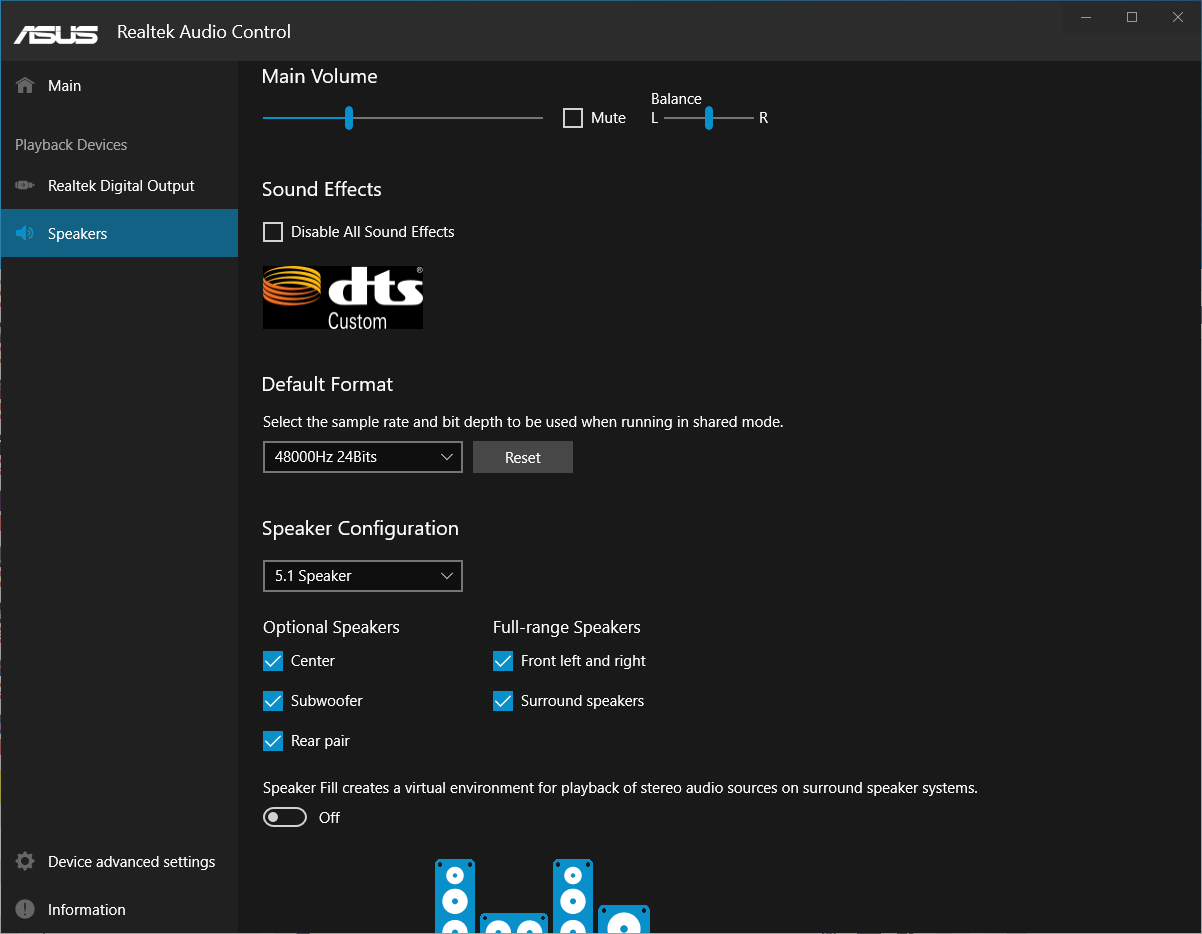
I had to configure the Z-5500 to be 6.1 Direct as my motherboard did not have a coaxial or digital audio outlet – something to think about for future upgrades. Then had to open my Realtek Audio Control, and set the Speakers to 5.1 Speaker, then can use the microphone and line-in jacks as outputs to the Z-5500.
This is part 1 – when I get the longer screwdriver, I hope to proceed with this repair. However the sound from the Z-5500 is so nice that I won’t use the repaired speaker set here, but will use it on another computer.
Sometimes I get an easy one. Last Sunday, I had visited my sister on my way home from badminton. She lives nearby and had helped stitch a curtain for us and we were picking it up. Anway, later that day, my brother messaged me that he had dropped off a tablet at my sister’s. I replied saying that I would pick it up the next day.
As it turned out, I was a bit busy that day so didn’t make it. Then the next few days were also busy – as I had started a part time Tafe course. Certificate IV in Cyber Security – it runs three nights a week and I found that there is also assessments that need to be done and research and other study on our own time. I had already done some other previous Cyber Security certifications, but wanted to do this Cert IV as a refresher course and to help reinforce the knowledge gained from the previous courses.
Yesterday, my brother messaged me about the tablet – which I had completely forgotten about, must be due to old age. I said I would pick it up on Sunday, which was today, and so, after badminton, I popped over to my sister’s place and she gave me two tablets. One was from my brother – a Samsung Tab S2 and the other was from my second sister, something about a battery life problem.
My brother mentioned that he had replaced the battery and that afterwards, it just wouldn’t power on. I got the tablet out of its case, and noticed that the back wasn’t sitting properly – so after sliding my fingernail around the edges – the back was loose and could be removed.
I verified that it would charge, by connecting a micro USB cable to it and sure enough, after a moment, the display showed the battery capacity around 98%.
I disconnected the cable, then did a visual inspection. I noticed a connector on the side which had dimples on it – where contacts would fit, but could see no contacts on the back that had been removed. Continuing on, I checked that the battery connector was in place – which it should be since it was able to charge.
Pressing the power button caused no reaction from the tablet, then after further inspection noticed that the five contacts on the connector seemed to match with five contacts on the main board. Apparently this connector is meant to be flipped over and sit on top of the other five contacts. Retrospective review of the back also showed that the connector sits in a little frame and is held down when the back is put back on.
This connector is meant to be flipped down and sit on those five contacts on the edge of the board.
I flipped the connector over, so that it sat on the contacts, pressed the power button, and sure enough – the tablet powered on. It looks that the design is such that if the back cover is removed – it prevents the tablet from being turned on – sort of like a fail safe to prevent damage when poking around inside the tablet. The back of the connector has some sticky surface, which might be why it stuck to the side of the case.
Anyway, it was a relatively easy matter of aligning the back cover with the small molded frame and then press all around to clip the back cover back into place. After doing this, I put the tablet back into its case, then pressed the power button – Voila!, it turns on. Fortunately the cable on that connector had not been damaged by being bent over like that.
So this was an easy job – I wish they were all like this. Another successful Repair.IT. Next is to see about the other tablet.
A month or two ago, my brother brought over to me, a Dell Optiplex machine. The complaint was that it couldn’t connect to the network. We had chatted briefly on WhatsApp about the problem – that his Dell has no internet, can’t locate lan connection, and can I bring it over tomorrow.
The Dell PC was dropped over, I wasn’t home, but my son was. When I got home, I set it on my test bench and connected everything up. Then had to contact him for the password, which I got in due course. Windows 11 was running on it, it logged on ok, but had a bit of an issue with the network, but after doing a few things, it was working – there was really nothing wrong, just that I had plugged the network cable into one of my lab networks, and my dhcp wasn’t turned on.
I don’t like to connect strange (as in not mine) machines to my home network, so have a number of different test networks that I can plug into. Anyway, the Dell was able to get an IP address. I ran the Windows Update which ran and downloaded a couple of months worth of updates and then put it aside. After a couple of days, powered it on and checked – yeap, still working. After doing a few checks I then packed it up.
What sort of checks do I do, you might ask? Generally the following:
Visual inspection of the network socket – check to see that all 8 pins are intact, i.e. not bent out of shape, or touching each other
Run Device Manager, check that the network device has a valid device driver – or update the device driver. Sometimes you see if with a yellow exclamation mark, which means there is a problem with it.
Check in Network and Internet settings, Ethernet – that IP assignment is Automatic (DHCP).
I look at error events in the System log, through the Event Viewer. It did show some errors about duplicate computer on the network – and was corrected by disabling netbios over tcp/ip.
Anyway, nothing else was untoward with the Dell PC, so my brother was informed – he said he would pick it up another day.
I don’t usually write about mundane things like this, but anyway, a week ago, he did come over to pick up the Dell PC. Then a few days later, he rang and said that it still wasn’t working.
I went through some standard troubleshooting. Was it connected direct to the router, or via a switch. He said it was through a gigabit router – D-Link. He sent me a picture of it.
I saw one orange light – and thought at the time, that was a bit strange. Actually I should have paid more attention. As he mentioned router, I thought that having one light lit was ok, so his Dell PC wasn’t connecting.
I then suggested setting a static IP address if he knows what the IP addresses should be like, and helped him to enter the right information – still no go. Next was asking if the router had been rebooted, he said that he had just done that – ok.
I suggested that if he had a USB Wireless Adapter, he could use that. Or if he has another laptop or something to plug into the same cable.
Anyway, he came back to me the next day saying that he fixed it. It turns out that he thought his laptop was working, but actually had been on Wi-Fi. He turned off Wi-Fi and connected to the network cable, and it didn’t work – just like the Dell didn’t work. So he went to check the cables from the NBN modem (which is actually the router), and eventually found that the cable from the router to the D-Link switch had come loose.
That was why I could see only one orange light in the photo. I should actually have had a closer look and seen that it was a D-Link DGS1005A 5-port switch and then asked about the cables at that time.
Anyway, the problem was solved, and I should have actually paid more attention to the information provided to me. Double check what is said – he said router, but the photo of the device had no antennas on it, and shows that it is in fact a switch – ok, live and learn, do better next time.
If I had gone through more of this troubleshooting, he might have been able to fix it without having to bring the Dell PC to me.
My younger son recently built a new gaming PC for himself. He wanted to play some newer games that his older PC could not do at the framerates that he wanted. Another reason was that occasionally, the old PC would not boot up – and he would have to try numerous times. During the Covid lockdown, computer parts were ordered from various suppliers and eventually arrived. He was able to build his new PC. A brand new custom built PC powered by the latest 12th generation Intel Core i7-12700K. The build was completed eventually and he took it home and has been using it quite happily except for other problems.
A couple of weeks ago, he was having trouble with his Superloop NBN service – his router wasn’t functioning, as he could connect via wireless, but could not access the internet. We had a spare Asus RT-AC68U router, so I went over to help swap over his old TP-Link AC1750 to this Asus router. It went well, and I also plugged in a network switch in the study so that both computers would have an ethernet conenction. I asked about the old computer and was told that it stopped working some weeks earlier. I had a quick look at it while I was there and it just would not boot – power would come on, but nothing on either display was visible.
I took the old PC back home with me together with the TP-Link router. The TP-Link router turned out to not pick up an IP address from the NBN modem, as I had plugged it into my Telstra Smart Modem and could see that it was not connecting. Then I set a static IP on the TP-Link and it worked. When I set the TP-Link back to dhcp, it picked up an IP address and was working – something must have gone wrong with the configuration as it wasn’t working before and now it did. Anyway, this article is not about that router but about the old PC.
This particular PC was comprised of a Corsair case, with a Gigabyte GA-Z97X-Gaming 3 motherboard. It had an Intel Core i5-4690K processor and 8GB of ram. It also had a Radeon RX-570 graphics card in it. The processor cooling was a Corsair H100i liquid cooling kit, which I had previously written about in 2014 – https://j0hn88.wordpress.com/2014/12/16/repair-it-of-course-corsair-h100i-liquid-cooling-standoff/
During that build, a standoff had been broken which I repaired. Now, back to the PC. I plugged in my diagnostics card – a Debug King card into the PCI slot. It was awkward to view the display as it was facing towards the power supply, but I had enough of a view to see what was going on. When I powered up the PC, I could see that the debug card was show that voltages were available, but didn’t seem to change status. This was almost as if the main bios wasn’t running. I tried various things, like pressing keys on the keyboard, but nothing appeared to work.
There was no PC speaker plugged into the motherboard, so I scrummaged around in my parts boxes and found a speaker with the right plug to fit the motherboard. Powering on again – effective silence. A beep would have be good, to show that it would try to boot, but nothing. A search of the internet showed that a lot of people had been having this issue since 2016 or so, but no real resolution to this problem.
I removed the Radeon RX-570 graphics card and connected the monitor to the motherboard DVI port. Still no display. I decided to verify that the Bios was doing something, by removing the memory. By powering up the computer without memory, I should get some error beeps. Sure enough, I get a constant beeping – so that was good, as it means that the CPU is most likely fine.
I plugged the memory back in, but in the other slots – I had a bit of trouble inserting the memory as it just didn’t click in as it should but was definitely locked in place. Powering on again, I saw that the behaviour had changed. The debug card was showing memory check then eventually display check, and then i felt that it should work. About half a minute later, there was a short beep from the speaker, and the bios screen was displayed on the monitor – ok, some success.
I didn’t have the hard disks connected, so powered off, connected the disks and powered on again. Success, I could see Windows had started up and then a login screen – great. I didn’t have the password, but was able to shutdown. Now let’s try the Radeon RX-570 graphics card. It was installed, then powered up – and … the original problem happened – there would be a period click from the speaker as the computer reset itself. Could the graphics card be faulty – I didn’t think so, but all I could do is to power off, and remove it. On power up, there was no change in its behaviour – constant reset was happening.
This is very strange – it worked a moment ago, before I put in the graphics card. Let me try removing the memory again so did this and then install the memory, power on, and the computer would boot up. Some success at least – removing the memory somehow forces it to work again, when the memory is installed again. I had some spare memory and tried that as well – works with my memory, but if I put the graphics card back in, then it caused the computer to fail and stay like that, until I do the memory trick.
So what is happening and why does the memory trick seem to work. Removing the memory must change the cmos settings, such that installing memory causes an update to the cmos which then works. This seems particularly like a bios problem. Once it was working again, I checked and found that the bios was version F5 which was the latest at the time of the build. I saw on Gigabyte’s website that there was an updated F8d bios in 2016 – with improved memory compatibility. I also replaced the cmos battery – which was a CR2032 lithium cell. That didn’t seem to change anything, but at least it was a new battery.
On Tuesday evening, my son popped over for a visit and I showed him what I had found – once the PC was working, he logged on and we could see that it was functioning, but putting a graphics card in, would definitely kill it. I downloaded the F8d bios, then once I did the memory trick and it was working again, I plugged in the USB and restarted into the Q-Flash mode by pressing the End key during the BIOS startup.
The BIOS firmware update to F8d proceeded smoothly and the system was still working afterwards. I shutdown and installed the graphics card, and powered on. Well, what do you know? The graphics card was working this time. I connected a network cable, and let the computer do its Windows updates, and restarted it a few times – still working, so then shut it down. I told my son that I wasn’t sure if it was fixed, so he can leave it a few more days.
The liquid cooling system was full of dust – that is the heat exchanger – so it was a matter of taking the fans off and vacuuming the heat exchanger carefully. I could see that there was still dust in it but this would have to do for the time being. I disconnected the power and will come back to this PC in a couple of days. I wouldn’t be confident that is is fixed, until the computer consistently boots up, no matter what I do to it, like remove graphics card, install graphics card, swap memory etc.
On the Anzac Day long weekend, I had a chance to do further testing. Put the original memory back in, still ok. Remove the Radeon RX-570 – still ok. Put it back in, still booting fine. I left the power off, switched off at the power supply. Various combinations of the above and still booting ok. So it looks like the computer is behaving properly, and I am now confident that the original problem has been resolved.
What would have been the root cause? Possibly, the Bios might have been corrupted – but maybe unlikely. The Bios Cmos settings could be another cause. By removing the memory and installing the memory causes the Bios Cmos settings to be updated. Updating the Bios firmware will also update the Cmos settings. I also feel that this motherboard did not have sufficient support under the memory slots.
Usually the ATX boards are a bit deeper, but this one is not as deep, so the memory slots overhang past the last screw fitting. My other boards will be deeper, allowing an extra screw to go into the highlighted support port. Originally, the memory was in the grey memory slots, but now I have left them in the black slots. Memory inserted in the last grey slot might not have been making consistent contact. I usually try to support the board when inserting memory.
Anyway, it looks fine now – hasn’t missed a beat with booting up – so will let my son take it back next time he comes over.