Retire.IT – Rest in peace – Black & Decker GL570 Line Trimmer

There comes a time in any machine’s life, that unless it is capable of self-repair that eventually the law of diminishing returns kicks in. Sadly this has now happened to my Black & Decker GL570 Line Trimmer that I have been steadfastly maintaining to this day. The actuator that enables the line to be extended began to have trouble soon after its repair the second time – due to the hole in which the actuator rotates that was getting enlarged, hence the actuator was not rotating freely and was not doing its job. Today I was trying to trim the edges after a hiatus of a month or more, the growth was a bit too much – the motor was getting hot from the heavy cutting and threw its bearing. When the bearing came off, the motor ground to a halt, and the actuator pin snapped off.

After opening it up, even after 10 minutes, the motor was hot to the touch. Perhaps this is now the time for this faithful line trimmer to rest in peace. Shall I “Retire.IT“? I.e. allow it to rest in peace or perhaps look to see what can be done with its component parts.

SONY DSC

Here is the motor with the bearing that has come off – that is the little brass piece. I could put the bearing back in, but due to the nature of the motor and its housing, there isn’t anything to stop it coming back out – unless I make a stopper to block the bearing from sliding off.

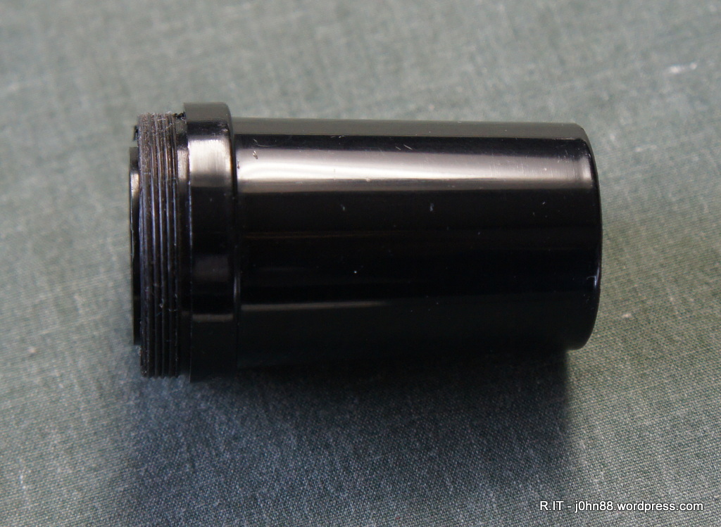
Now this might be a good time to see about removing the line spool housing from the motor spindle. If this can be done without damage to the spindle shaft, I might be able to use or repurpose one of the after-market cutting heads. If I can do this, then this line trimmer could live again with perhaps a Little Juey head.

We don’t usually rush in as we also might need to work out the economics of the situation. A replacement cutting head would cost about $32 but a cheap new line trimmer like the Ozito 550W is only $50.  If I go for a new line trimmer, it will most likely be in fine working condition and will generally work within its guarantee period.  After it goes out of warranty, I might eventually end up in the same situation with having a line trimmer that isn’t working well.

Maybe the solution is to attempt to remove the line spool housing from the motor.  If it could be done without damage, then perhaps design and make a new trimmer head for it that is either similar to the commercial heads where it is easy to replace the line.  Failing this, then buy a new line trimmer, and think of a use for the motor from the Black & Decker.

Reassemble.IT – Meade 6x30mm Finder Scope – again!

After I posted the earlier article about this finder scope, I had a thought that perhaps I should check the focal point to make sure that the crosshair reticle is in the right place. The finder scope works as it is, so the lens arrangement is correct. It turns out that I was wrong yesterday – the order from left to right is as follows:  The end piece, then the crosshair reticle followed by the big spacer, then the lens arrangement as per yesterday.

SONY DSC

When I assembled it this way, I could look through the eyepiece and see where the original crosshairs had been broken and curled up against the sides of the reticle.  Sure enough under a 10x jeweller’s loupe, I could just see the broken hairs.  Anyway, it doesn’t make any difference to the focusing of the finder scope as the lens arrangement dictates this, but it now means that when I do find something thin enough, I can fix the crosshair reticle.  So, now again, I have “reassembled.IT” properly this time.

P.S. The second piece from the left is the crosshair bit. It has four tiny slits on one side of the ring. The side with the slits should be on the right as viewed above.

Reassemble.IT – Meade 6×30 Finder Scope

Six months ago, I bought a second hand Meade LXD55 SN-6 telescope. The LXD55 is a computerized mount that is capable of slewing to any object in its database. The SN-6 is a 6-inch Schmidt-Newtonian telescope. I noticed at the time that the Meade 6x30mm finder scope was mounted backwards. The finder scope is a small telescope so usually the big end points to the sky and we look through the little end, however they were looking through the big end – strange.

SONY DSC

Yesterday, I was reminded about this finder scope, so decided to have a closer look. I looked through the finder scope and realized why they used it this way. When viewing through the eyepiece, everything was blurry – a case of not being in focus. To focus the finder scope we have to move the eyepiece section and front lens apart, i.e. move the eyepiece in and out of the tube. Or move the main lens in and out, but no matter what I did, it would not focus. After taking the eyepiece out, I worked out that the tube was about half an inch too short. How is this possible?

SONY DSC

A search through google mentions that some Meade finder scopes also had this problem, and the solution was that the supplier would replace it. This telescope was first released in 2002, so now it was way past its warranty. The only solution now is to work out what was wrong with it.

The eyepiece appeared strange, so I decided to take it apart, noting in which order the pieces came out.

SONY DSC

It was strange – the piece on the right end is obviously for the crosshair reticle, which should be in the middle.

SONY DSC

Both eyepiece lenses are half-convex and judging by the thickness, they should be arranged as a standard Kellner eyepiece.  A Kellner would have the two lenses separated by the small spacer with the thicker lens on the right, with the curved surfaces facing inwards.

SONY DSC

This lens arrangement would then be on the right.  In the middle would be another spacer, then the crosshair ring – which didn’t have crosshairs, and the final piece on the left.  Once I “reassembled.IT“, this is what the eyepiece looks like – quite different from the original which must have come apart and then the owner didn’t know how to put it back together.

SONY DSC

Once the finder scope was fully assembled, it was able to be focused on short distance by moving the eyepiece outwards, and to focus on long distance by screwing the eyepiece inwards. Another thing fixed.

P.S. The crosshair reticle, if it had one, would be at the focal point of the lens arrangement, which can be worked out by looking through to see at which point the image is sharp and focused.  I just need to find some very fine wire or hair and glue them to that piece. Alternatively, use a piece of clear plastic of the same diameter and scribe or draw a couple of fine lines on it.

P.S. I updated this with another post at this link to show the correct spacer arrangement – https://j0hn88.wordpress.com/2015/04/14/reassemble-it-meade-6x30mm-finder-scope-again/

Repair.IT – Technics SL-Q3 Automatic Quartz Direct Drive Turntable

It seems that their might be a vinyl revival happening, at least that is one of the topics on Australia Wide, ABC on Friday.

A friend brought over a Technics SL-Q3 automatic quartz direct drive turntable that she recently acquired. It seems that after getting it home, only the left channel was producing sound. After the customary swapping of RCA cables, it was still only the left channel. I suggested removing the head shell, and putting back in, but somehow the communications got crossed and she removed the screws holding the cartridge to the head shell – no matter, just fasten it again – but apparently it was not possible – which was part of the reason the turntable was brought to me.

On inspection, it was quite obvious – the cartridge is a moving magnet type of phono cartridge so the nuts that the screws connect to, basically moved in towards the magnet. I used tweezers to pull the nuts back out, then fastened the cartridge.  I showed her how to remove the head shell, and put it back on – ok.  Next I connected up my phono pre-amp and then connected the output to a pair of amplified computer speakers.  Sure enough, there was no sound coming from the right channel.

After a bit of troubleshooting, measuring the cartridge outputs, and getting 400 ohms on the left channel, and 386 ohms on the right channel, I conclude that the RCA cable was at fault.  I turned the turntable upside down on its lid, after locking the tonearm. The base was easily removed by unscrewing the four spring loaded feet.

The view of the insides of the turntable was quite interesting, there was a loose wire loop sitting on the circuit board – obviously, that isn’t right.  It seems to be connected to the repeat or memo slide button – but where should it go. After a brief search of the internet I located a photo of this turntable with the wire loop intact. From this I was able to loop the wire first around a drum, then the other end also around the drum in the opposite direction and finally around two little pulleys.

SONY DSC

That looks more like it. Then remove a metal shield and so the RCA output cable connections were accessible. I was able to measure continuity from the RCA cables – left inner, left outer and right outer. Right inner – the red wire was not connecting at all – so it seems that the red RCA cable had failed. At the same time, I decided to check continuity from the cartridge to this connection board – the red wire wasn’t connecting – strange, anyway – sort this out after replacing the RCA cables.

SONY DSC

The next morning, I located a new RCA cable in my assorted cables box, then cut and arranged the ends so that i could solder them onto the board after removing the old cables.  The above photo is a shot of the connections after the new cable was soldered. The little piece of sticky tape is just to provide a little insulation before the metal shield is screwed back on. I checked the cartridge at that point and I was seeing both channels ok – weird.  So it looks like I have “repaired.it“. I played a few LP’s to check that it was working and it was.

Today I thought I might check it again as my friend still hasn’t come over to pick it up. When I powered up, I was getting a loud hum from one speaker – it would reduce if I connected the ground wire to the pre-amp output ground, but would not disappear. I switched left and right inputs and the hum swapped speakers – ok. Unplug the input cables and measure the resistance – right channel ok, left channel not ok – what gives. I unscrewed the head shell and plugged it back in a couple of times, now I get no hum. It seems that the spring loaded contacts in the socket of the tonearm may be the problem. This can happen if the spring in one contact is particularly weak or some debris is in the sliding surface that might cause it to jam. This was probably what happened with the red wire previously except now it was the white wire. Anyway the fix is to unscrew the head shell, then push it in and out of the socket a few times to give the springs a bit of push, then release, etc.  Now all is well and I played my favourite LP – Solitude Standing by Suzanne Vega.

P.S. The dust cover or lid of this turntable has broken off at the hinges. Also it was very cloudy, i.e. not transparent. It would require replacement so the hinges were removed.

SONY DSC

I thought I would give it a try of using Maguiar’s Plastx plastic polish to see if I could brighten it up, and after working on one corner, I could definitely see the difference. Anyway, I can’t do all the work, she should do some in her spare time – it will need a lot of time to polish up but the fine scratches will still be there unless we do a thorough sanding down and then polishing.

SONY DSC

Can you see which corner I worked on and see the difference now?

Repair.IT – Eagnas electric tension head – coarse tension adjustment.

A while ago, I had this Eagnas electric tension head come in – together with its twin.  I repaired the other one quickly but this one wasn’t acceptable because the tension that it would pull was much higher than the display reading.  I.e. when set to 20lbs, it would pull at about 30lbs.

I did look into this further and eventually worked out how to adjust it.  To adjust the tension that is required, we rotate a knob on the side of the tension head.  By doing this, a spring is loaded up or unloaded as the case may be.  Also at the same time, by rotating this knob, it moves the sliding contact of a potentiometer.  The electronics then reads the potentiometer resistance that is set by the sliding contact, and then displays the result.  To tension the string, a button is pressed, then the motor turns until the tension of the string exceeds the compression force of the spring, allowing a microswitch to be activated.  If the string stretches, and it does, it will relax the tension allowing the microswitch to be deactivated, then the motor pulls and so on.

The problem with this machine is that the display tension and the resulting tension are way out.  I had a look at the spring and yes, there was a knob that is on a bolt that could be turned to reduce the spring tension.  The problem was that the knob was smooth and could not be turned by hand or even with pliers.  The only way to adjust this was to remove the motor mounting, to unload the spring, then turn it with vice grips and then reassemble it.  After doing this, I was able to get the resulting tension to be lower.  Ok, so I need to adjust it again – then I had a bright idea – this happens from time to time.  What if I take that little knob out and knurl the sides so that I can adjust it in the machine using pliers.

SONY DSC

Since today, I was out in my workshop drilling holes in the stringing machine turntable base, I thought it was an opportune time to do this job.  I took the knob out and decided to put a straight knurl pattern on it, instead of a diamond pattern. I mounted the knob onto a M8 bolt and put it in my lathe, then using the knurling tool to cut the pattern. The photo above – shows the spring with that knob on it.  Now I can properly adjust the tension easily without disassembling the whole thing.  Maybe I should patent this!

Relocate.IT – Spinfire Blaze stringing machine turntable base end posts

Last Friday evening, a friend brought over the turntable base from his recently acquired Spinfire Blaze stringing machine.  This stringing machine has fixed end posts that allow for mounting a tennis racquet with the side supports in the appropriate place.  The problem is that my friend only strings badminton racquets which are smaller in size than tennis racquets.  The badminton racquet can be mounted but then the four side supports are only supporting the racquet near the ends instead of near the middle as they should be.

After some taking of measurements with a badminton racquet mounted and a bit of scratching heads, it was determined that we need to move the end posts closer by 5-6 cm. The end posts are fastened by M6 bolts – with a four hole pattern that we saw is separated by about 2.5cm.  Suddenly we had the light globe event – a bright idea, how about we mount the end posts by using only the two closer screw holes, which should move the posts together by 5cm.  We did this and sure enough – the badminton racquet could now be mounted with good support on the sides – sufficiently close enough that now we could be confident of stringing these badminton racquets without worrying about the racquet head turning circular or breaking.  Since it was getting late, we would leave this until I have some time during the day.

Today was the day to “relocate.IT” the end posts, that is. I stuck some stickers on the base where I expected the new hole to be, then measured across by 25mm and marked the centre of the hole.  But when I look down the base, it appeared that the centres were not quite right.  I had another bright idea, I could just drill a template – which is what I did.  I got some scrap aluminium flats, and drilled three holes each 25mm apart.  I could do this on my milling machine, because the X axis has a dial that has incremental marks every 0.02mm.  Of course, a full rotation was 1.5mm, so a matter of a bit of maths or just counting the rotations, to get the 25mm required.  Two holes were drilled at 6.5mm then the third hole was drilled at 3.3mm.  I have an automatic centre punch which has a tip about 3.2mm in diameter, so by lining up the two existing holes on the turntable base, I could punch the centre of the third hole – the one I need to drill.  After doing this, I could see that the punch put the centre where it should be, and a bit different from my original markings.

SONY DSC

Here is a picture of the base with the two holes punched, the template and the automatic centre punch. Now to mount it on my little milling machine.

SONY DSC

Here I have it mounted, and a center drill in the drill chuck – the center drill is used to start the hole, and allows me to adjust the X-Y table to properly center the marking, then drill it. The base is aluminium, so after drilling the center hole, I went straight to the 6.5mm drill. If this was a steel base, it is better to use an intermediate drill like 3.5mm before the 6.5mm drill.

SONY DSC

After drilling both holes, it was time to swap the ends around and do the other two holes. Then use a countersink tool to clean up the edges of the hole so that it does not have sharp edges, then to reassemble the end posts.  My friend also invested in automatic base clamps, so I installed the base clamps before I installed the end posts.  The end posts have one control to move each pair of side supports in and out, so after mounting the end posts, I also had to mount an actual racquet, then adjust the end posts so that the side supports with clamp the racquet at the same point.  Only a minor adjustment was required, then retighten the end posts.

SONY DSC

And now here is the final product sitting on my tile floor.  The result is that the posts have been moved 2.5cm towards the centre on both ends.  Now my friend can use this machine to string badminton racquets.

Re-lubricate.IT – Silencing a quartz clock

Just last week my mother had moved into a nursing home.  She is in a room where there is no clock, so my sister initially thought about buying a new clock that was less noisy than the clocks already at home.  She found an article on the internet that talked about oiling a clock to make it silent or close to it.  She brought over two cheap wall clocks, that I remember and could hear – each tick could be heard if you were within 10 feet of the clock.  I was skeptical as I could not understand how a little bit of oil would make a clock mechanism go quiet, but was prepared to try it out.  Worst case is that the clocks no longer work and since these are cheap, like $5 – it was worthwhile to use them as guinea pigs.  It was time to “Re-lubricate.IT“.

SONY DSC

I placed the clock face down, and one clock was held by little clips, so I just rotate the clock insert anti-clockwise, and it would unclip, then lift it out of the glass and surround.  Pull the hands off – they are just press-fits, and if they get bent, just straighten them.  There is a nut holding the clock mechanism to the clock face.  Then the mechanism can be taken out the back.  A few little clips hold a cover on, and then we get to the mechanism.  Essentially there are a few gears, like 5 or 6 – just remember in what order they came out.  Put a tiny drop of oil on each spindle or swivel point, then put it back together and voila!, much to my pleasant surprise, the clock was much quieter.  It was unbelievable!

I did this to the other clock, which we had put on a table with a cushion on top to mute its ticking.  This one, the back was held on with six small screws, but then after removing the hands and retaining nut, the mechanism refused to come off.  After much fiddling with a knife to go into the gap, it finally came off, it had been glued in.  Anyway the same process of “Re-lubricating.IT” and we ended up with another clock that was so quiet, it was hard pressed to hear which one was the louder one originally.

One thing when reassembling the clock hands, is to make sure that the second hand and the minute hand does clash – just bend slightly one of the hands to make them more parallel.

Just imagine, if this was done in the factory, a lot of us would not be trying to sleep at night listening to the ticking of a clock.  This is worthwhile to do for those that don’t have digital clocks.  Now, I hear that Ikea has $2 kitchen clocks, so if you manage to make a mess of this, a cheap replacement is available.  Also, the mechanism in most cases are compatible as they are usually copies, so your favourite clock can be rejuvenated, by replacing the mechanism – and if you are lucky, you can even use the old hands.