Recondition.IT – Thurlby LA-160A Logic Analyzer – Part 1

Towards the end of last year, I came across an interesting circuit board on eBay. It was the CY7C68013A-56 EZ-USB development board – made by Lcsoft. Perhaps made is too strong a word, let’s say “designed” by Lcsoft, and copied by the myriad of asian suppliers. Anyway, it was less than AU$8 including shipping, so I ordered one. In due course, it came, but by then – as usual – I was tied up with other things.

Over the last couple of days, I was sorting things out, and I pulled out my Thurlby LA-160A Logic Analyzer from my cupboard. This logic analyzer was bought at great expense back in either 1985 or 1986. This one was badged by RS Components and was 16-bit capable, with various clock and trigger inputs – very versatile and economical at the time, compared with others that there were available and completely unaffordable, at least to a small business.

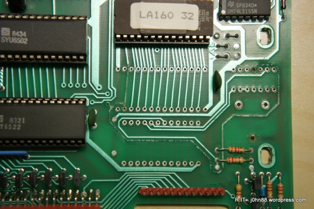
I was doing repairs on computers at the time, mainly Commodore 64’s and the IBM PC/XT clones. From memory, it didn’t get used a lot, and still has the plastic that covered the display. Being on a small budget, I elected to make the data pods for it instead of buying them. Ok – to stop digressing, I powered the LA-160A up and could see the display go through a check of all the segments, then LA160A .32 was displayed, telling me that it says that it is a LA-160A and the rom version is 32. Shortly afterwards, it said ready – but then a short while later, started checking the display again, then coming back to LA160A…

It looks like something is slightly amiss with it, so I had a quick check of Google, as we usually do, and found an article about the Nicad battery, and how it could leak. Definitely after 30 years or so, a Nicad battery will most likely have self-destructed, so it was time to open it up and take a look.
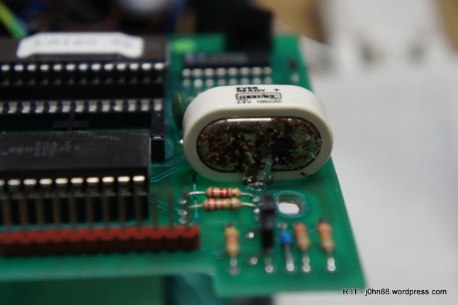
SONY DSC

Nicad failure

For sure, the battery looked a bit worse for wear – the negative terminal was corroded. Not only that, it looks like the electrolyte leaking out of the battery has travelled quite a distance.
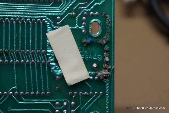
SONY DSC

Under the board

Here the tracks under the battery appear also to be corroded, as in eaten away under the PCB coating. I had to remove the battery, which was easier said than done – the positive terminals were easy to desolder, but the negative terminal wouldn’t. I did manage to get it out finally and then it was time to inspect the damage.

SONY DSC

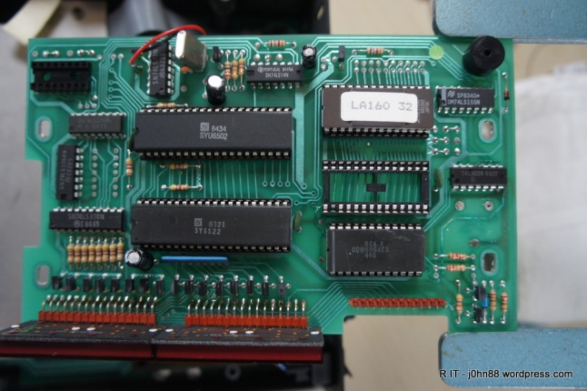
LA-160A controller board

The top of the board shows where the electrolyte has followed the path of corrosion, a process called wicking where the liquid moves into small gaps, caused by corrosion. I could see that the corrosion has reached pin 11 of the 74LS02N chip on the right, then the track in the other direction has gone under the two resistors, under the 6116 static ram, then all the way to the empty 28-pin socket (for an option rom) where pin two is corroded.

The corrosion will not stop and must be cleaned. I cleaned the bottom of the board first, since there was not much to be done, except that the tracks were larger.

SONY DSC

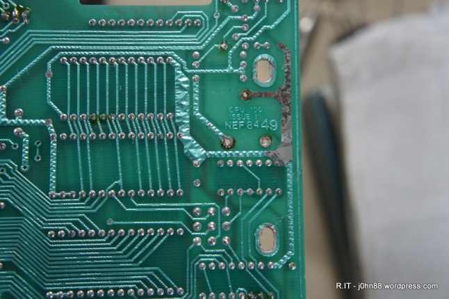
Corroded ground tracks cleaned (sort of)

I removed the 6116 chip, then desoldered the 74LS20 and both the 6116 socket and the option rom socket. After doing this, I continued the cleaning process – by using methylated spirits with cotton tips to clean the tracks that were corroded – to try to neutralize the electrolyte. Once it was dry, I used a small flat screwdriver, and a fibreglass pen to remove the majority of the corrosion, then cleaned again with metho. Once I was happy with it, I gave the board a clean using isopropyl alcohol cleaning wipes (as the metho leaves a white deposit).

SONY DSC

controller board after cleaning

Now it looks better. I could see that the corrosion had been moving in the direction of the LA160 32 eprom, so it looks like I caught it in time to prevent any major damage.

The next steps to do will be as follows:

  1. Repaint the cleaned tracks with a PCB Resist Touch Up paint, preferably in green. This will protect the tracks.
  2. Refit the 24-pin ic socket for the static ram and install the 6116 chip again.
  3. Fit a 14-pin ic socket for the 74LS02N.
  4. Check if I have stock of the 74LS02N, if not – then order a couple – I like to keep spares.
  5. Check continuity for all connections relating to the damaged tracks. Jumper wires to be soldered in place as needed to fix damaged connections.
  6. Order a replacement battery 2.4V 100mAh. Nicad ones are not available, but a NiMH 2.4V 140mAh battery is available at one of my usual suppliers. If I do this, then I need to ensure that the logic analyzer is turned on every couple of months or so, to keep the battery charged up. It is usually a flat battery that starts leaking, plus of course – old age.

I have decided not to install a 28-pin option rom socket for the simple reason that I don’t have the LR-64 option rom for this logic analyzer. If I do get hold of one and want to install this, it would be a simple matter of installing the socket at that time. Also leaving the socket out would allow me to inspect the corroded tracks to confirm that the corrosion is no longer progressing.

By the way, the LA-160A will capture 16-bit data at 10MHz sampling rate. The little CY7C68013A board will be able to capture 8-bit data at 25MHz – an example of new technology at less than a hundredth of the cost of the LA-160A. For about $100 I could get a logic analyzer that can capture 34 bits at 125MHz – maybe that is for another day.

Anyway, this is part 1, with more to follow.

P.S. During my Google search, I found a site http://sonicsheep.com/Electronics/3-LA160%20Writeup.htm that talked about the battery and had a newer rom version 50 available for download, and from another site

http://k1.spdns.de/Vintage/Sinclair/Other%20Inventions/Other%20Electronics%20Products/

found a service manual for this LA-160A. To try out the version 50, I will need a 2764A eprom or perhaps a 2864A eeprom. The 2764A is uv-erasable, but I don’t have a uv eraser, so the 2864A being electrically-erasable would probably be better. Anyway, it depends on what is available and from where.

[Edit]  After checking my stock of integrated circuits and finally finding a 74LS20N, I found that I had misread the IC and actually needed a 74LS02N, of which I do have plenty. Updated the above article with 74LS02N. I should wear my glasses.

Retell.IT – 2013 – Repair of Eagnas Plus 8000 electronic tension heads for stringing machines, a lot of them

Recently the topic of Eagnas tension heads have come up, so I went back into my log books to look at a suitable article to write. So, here goes.

Back in June 2013, I was contacted to see if I was interested in repairing some Eagnas Plus 8000 electronic tension heads. I said that I was interested, and in the following days, collected four of these to look at. These tension heads are used for racquet stringing machines and are not cheap. Very little information was forthcoming about the condition of these tension heads other than that they were not working properly or something like that and they need to be checked and/or repaired.

Tension Head 1 would turn on but wouldn’t move – the gripper head was jammed.

Tension Head 2 had crumpled slide covers. This tension head would turn on, but as the gripper head moves,
it would jam on the slide covers, hence these covers are broken and crumpled.

Tension Head 3 would turn on, but soon afterwards would start beeping.

Tension Head 4 would turn on, but didn’t seem to be able to move the carriage. Pressing the nylon switch
lever to indicate the start of a string pull did not move the carriage.

Ok, so quite a few different problems. I started looking at the ones that would turn on.

To open these tension heads, I had to do the following – with Tension Head 3 to start with.

Unscrew the switch cover on the side of the string gripper. Knock out the gripper fastening pin allowing the gripper to be removed. The gripper housing and diablo is held by two machine bolts – remove them. There is a switch cable plug and socket arrangement, disconnect it by removing the glue surrounding it and then separating the connectors. Remove four bolts that fasten the head cover. Lift the cover on the left, then push the cover to the right to clear the power switch, then lift it up and tilt it towards the back. For better access, disconnect the display board ribbon cable. Now, we can also remove the slide covers, and then we can work on the tension head reasonably easily.

SONY DSC

This particular Eagnas tension head uses a geared motor with sprockets to turn a chain that moves a carriage on a slide, to which is attached, a gripper and a load cell. The gripper is mounted on top of a plate that is attached to the carriage about a third of the way down, and the other end will press onto the load cell. The load cell, being fastened to the carriage, is used to measure how much force is acting on it by this plate when the string is being pulled, indirectly by the chain. This seems to be a reasonable way of working and should be quite accurate and repeatable.

SONY DSC

Here is another photo of the mechanism. The load cell is the aluminium block on the left, you can see the chain, with lots of grease on it. There is also a fair bit of debris inside, metal shavings, drops of hot melt glue, etc – more on this later.

Continuing on, with opening the others …

Tension Head 1. Further investigation showed that the chain had come adrift, and wrapped itself around the motor sprockets. It seems that the chain’s master link had come off, and the master link’s side plate and locking plate were not to be found. I was able to connect the chain together temporarily and was able to confirm that the tension head appeared to be working, therefore I need to order a replacement master link to properly fix this tension head.

Tension Head 2. The slide covers were crumpled because they move in a slot that is not lined up with the carriage movement. Think of train tracks with the carriage in the middle – in this case the carriage was moving to one of the rails forcing the slide covers to crush. I was able to fix this by realigning the slide slots so that the carriage moved in the centre and parrallel to the slide. A bit of bending of the metal supports was what was needed.

Tension Head 3. This tension head had a noticeably loose load cell, but would beep again – so look at this later. Also it would not power up from time to time.

Head 4. Once I opened the tension head, I was able to find that a wire had come off from a switch. Resoldering this wire to the switch allowed this tension head to work again. I also found that the switch lever that is on the gripper was missing a spring. This lever is pressed in order to start the string tensioning. I was able to cut a similar spring to the appropriate size and fit it to complete the repair.

As the customer was in a bit of a hurry for a tension head to be ready, I took the slide
covers from Tension Head 3 and put them onto Tension Head 2. After that was done, it was reassembled and was tested to be working fine. Thus, I had two tension heads working and returned these two to him. He then gave me another tension head to look at that had been returned by a dealer.

Continuing on with these tension heads, I found that Tension Head 5 would turn on but didn’t seem to be able to move the carriage.

Quite a few different symptoms. Further work showed that several of the load cells were loose – not fastened firmly would mean inconsistent tension readings that would suddenly jump, not really a good thing. Another thing I found was that the carriage assemblies were sometimes very tight around the pivot bar due to the bearings being either too tight or too loose, and the side plates of the carriage not being parallel. This was when I found that many of the parts that hold the side plates of the carriage together are differing lengths, hence they used washers to adjust the width, and most of the time, ended up with screws that were too tight and others that were not holding.

I decided to rework these carriages by measuring the shortest support bar, and machining everything else to fit, so that without washers, the side plates would fit properly and the carriage was secure without excessive force on the screws. I also found some bearings had no grease, which explained why some were hard to turn. Regreased those bearings with lithium grease. The chains also had excessive grease on them which accumulated around the sprocket wheel – much of this excess grease was removed.

Load cells were adjusted and tightened – but not too tight, so as not to deform the load cell mountings. I also adjusted the contact point of the pivot plate where it presses onto the load cell – there should be a small gap, about 1mm or so when the system is idle without tension. Much of this work was spread out over several days as I did not always have time to work on these tension heads.

Tension head 5 – found that the motor connection was intermittent. On the other machines, the motor connector was glued together – this one did not have glue, but would work if I pushed the connector together and if I pulled it apart a little, it would stop working.

SONY DSC

That is the connector in the middle of the photo – I then tied the connector together and glued it so that it would not come apart easily. I also found a master link locking plate in the bottom of the tension head. When I connected the gripper switch, I found that the carriage would not move. One of the gripper switch cable connecting pins was slightly shorter and was not making contact. Just had to push the pin in further to make contact then glue it in place. Another tension head fixed.

Tension Head 3 – I found out that the beeping was caused by the knot tying switch on the control panel was nearly always pressed down. This was fixed by moving the control panel a little so there was no pressure on the switch. That fixed the beeping. Then during the testing, this tension head stopped working. After tracing the wiring, found that one of the wires going to the 240/110V voltage selector switch was loose – pushing it back in, allowed the machine to power up. Resoldered that wire and checked the others at the same time. Now this tension head was fixed.

I returned these two tension heads back to the customer, and he gave me two more to look at. That would be a total of seven machines in all.

Tension Head 6 would not turn on. The motor doesn’t make a little jump like some of the others, no display – nothing.

Tension Head 7 would not turn on. It was missing a 2A M205 fuse and fuse cover – that could explain it, but was it that simple?

I opened up Tension Head 6 and checked the voltage selection switch. Sure enough – one of the wires was adrift, it might be a common problem to look for in future. Resoldered this wire. Still no power – what is happening? I could see power going in then no power to the board. Eventually I found that some of the secondary windings had been cut due to the motor pressing onto the transformer – how is this possible?

SONY DSC

Ok, it was due to the way the motor is mounted and the lack of clearance to the transformer. We can see from the earlier photo with the motor connector, that the motor sits very close to the transformer – another thing that needs to be checked.

SONY DSC

Now after repairing these wires, I moved them below the top of the transformer before I remounted the motor assembly. After reassembly, the carriage would move when I press the switch, but it shows no tension reading – strange. I checked the load cell connections because the wiring looks different to the others. It looks like someone had played with it and reversed the red and black wires – I swapped it back around – still nothing. Anyway, it turned out after tracing through the circuit, that a transistor had failed – 2SC2236Y. I was able to get a equivalent NTE382 transistor to replace it. Still not working – ok, a long story short is what is needed – eventually I managed to determine that the ADC had failed. This was a Sony CXD1175 small outline ic that was no longer in production, but I was able to order a TLC5510AINS that was an equivalent.

SONY DSC

Sorry, the photo of the board showed the chip upside down – the one in the middle – that is why the board looks a bit strange. Anyway, removing this with the use of ChipQuik was relatively easy then soldering the TLC5510AINS using solder paste and a hot-air rework station was also uneventful. After a quick calibration adjustment, this machine was fixed.

Now back to Tension Head 1 – the 25H master links that I ordered came in eventually. The wrong links came in first, then they had to resend the right ones – it seems that both links had the same item code. Installing the master link allowed the machine to work, and after a quick check of calibration – this tension head was also ready to go, except that I had used its slide covers to replace those on Tension Head 3 that had been used on Tension Head 2. I bought some grey card stock and made new covers to fit this machine.

Tension Head 7 – the one that was missing a fuse and fuse cover, I replaced the fuse, but didn’t have a fuse cover. That was all that was needed to fix this machine – an easy one.

So, in summary, most of these machines had similar issues, problems with the carriage, load cell – wiring that was coming apart – they are generally manufacturing problems. Debris from manufacturing was also inside the tension heads – I vacuumed them out as much as I could before returning them to the customer. The missing chain link plates – could it be carelessness? If they had come apart, which is very unlikely, then I should have found the pieces inside, but then I found a locking plate in Tension Head 5, which wasn’t missing one.

Tension Head 6 was the one which required the most electronic repair, with the broken wires in the transformer from the motor pressing on it. I suspect that someone tried to fix it, by playing around with the load cell wiring – why on earth someone would do this – I don’t know, but that likely caused the transistor to fail, which then put more than 5V onto the ADC, something like 12V more likely – and that caused the ADC to fail. Did the ADC failure then cause the motor to continue pulling and cut the wires? There is a microswitch that should limit the carriage movement to prevent this happening – anyway, a combination of events came together that meant that this tension head was the hardest to repair.

In the repair business, we often get easy ones and sometimes hard ones. There is a 90/10 rule or is it the 80/20 rule?

Recondition.IT – Slide switch for crystal locked FM Radio

We have one of those three-channel crystal-locked FM Radio – commonly used for listening to the China Radio station 2CR and others.  It had been playing up at times and was unable to tune into any channel and was put aside a while ago.

It is a DP3T slide switch that is the problem.  Dual Pole 3 Position slide switch – with pin spacing at 2.5mm apart.  I was looking for alternatives and could find switches that have pins 2mm and 3mm apart, but not 2.5mm.  After some time, I was able to find a similar switch – a SK-23E01G, but would you know, I cannot find anyone who has stock of this switch.  I did find a couple of sites that do advertise this switch, but they require pre-ordering and have a minimum quantity of 1000 units – fantastic, except that I only need one piece.

My only option is to buy a new radio, or to “recondition.IT” – the switch that is.  The switch is used to select from one of three crystals that determine the frequency that the radio is tuned to.  I removed the switch from the pcb, then opened the housing.  It was immediately obvious that the switch contacts were worn and were oxidised.

DSCN5032

There are two movable contacts – but the fixed contacts are not allowing good contact. To fix this, I used a 240 grit emery paper, to polish up the contacts, followed by 320 grit paper.

DSCN5033

Now this looks better – at least the contact surfaces are shiny.  I reassembled the switch, then checked the switching resistance, and it was good.  Great, installed the switch, closed the radio, added four AA batteries, and voila – it was working.  Not bad for about 10 minutes work.