
Here is something that was on my bench for repair. A Highgate OL7664BK outdoor wall light with PIR motion detector. It is a nice light made from black metal housing with glass pieces which had been installed at a sister’s place during a small renovation, and then failed to turn on, a few months later.
After making contact with the supplier, a replacement light was sent out. In due course, the light was then replaced, and I was given the faulty unit – perhaps I could Repair.IT and get it working again.
After opening the light housing where the sensor is located, I found that the sensor unit is a small black box with the PIR on the outside and three wires going into it. Brown, Blue and Red – guess what these would be? Fortunately, they also went to a terminal block which was marked. Brown and Blue are standard colours for Active and Neutral, but Red’s marking was an X – ok, meaning switch.
Sure enough X went to the Active of the light socket, with Neutral being the common for the light socket. Also I noted that there was also a ground wire terminating onto a stud on the metal housing – that is very good indeed. Now, the light is still usable if we wish to use it just as a standard light fitting, without the PIR sensor by just wiring the input wires to the active and neutral of the light socket. However, I am interested in how to fix it.
The small black box was sealed, but nothing a rubber mallet couldn’t solve, so eventually the seal where it was either glued or plastic welded – came apart and I could get to the interior.
Inside was a small board that was connected to the separate PIR sensor board. Often the question I get asked, is how do we determine what the fault it. Generally we will know something about the device, in this case – it is a switch that turns on or off the light. The PIR sensor board does the sensing, so it must then use the small board to switch the light.
Usually this involves an optical isolator which is usually in a small 4-pin or 6-pin package. This optical isolator, or opto isolator will then somehow connect to a switching device, which is usually a triac. This small board contained a MOC3023 which is a known optocoupler with a triac driver output. From this chip, it connected to a triac via a small limiting resistor.
I examined and determined that a Triac had failed. In additional the small limiting resistor of value 200 ohms had also gone open circuit.
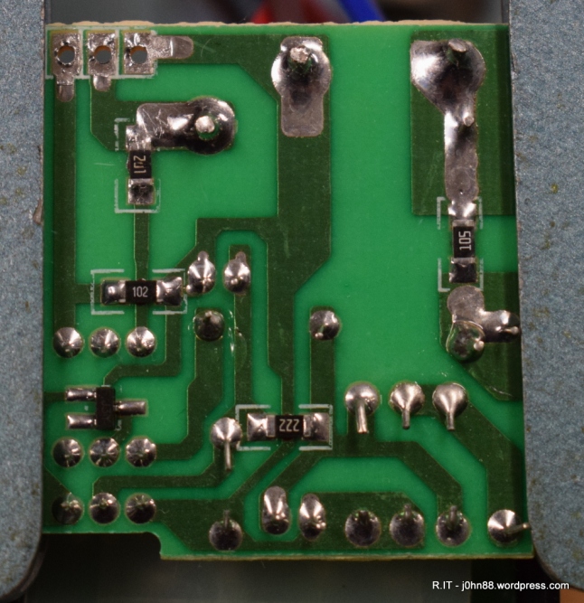
Likely what had happened was that the Triac had failed, and the ensuring high voltage caused excess current to flow through the tiny resistor which then failed. Or it could have been the other way around, but the resistor is slightly discoloured which meant that it had gotten way too hot. In this photo, the resistor is the one near the top left. The marking shows 201 but the 0 is a bit marred.
The marking on the Triac was a BT136-600E. My local Element14 supplier had these in stock, for around $1.26 but then ordering this by itself plus the resistor would incur a delivery fee much larger than the total. Since this was a charity repair, I elected to buy these parts on eBay. 10x BT136-600E’s were $1.86 delivered, so this was a good deal.
The resistor was a 200ohm surface mount version in a 1206 package – I managed to find a good supplier that would give me 100 pieces for $1.34 delivered. In the case of eBay, why buy 1 when you can get more for a similar price. It leaves me with lots of spares for future repairs.
The BT136 was easy to remove, just using my desoldering station – it was a matter of minutes to desolder each pin and remove it from the board. Similarly, but using a SMD tweezer soldering station, the resistor came off in a few seconds after heating.
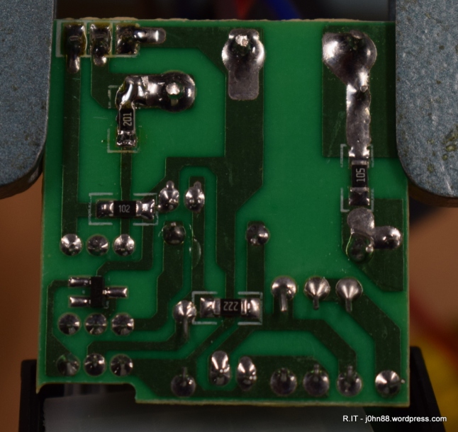
Once the parts came in, which was a few weeks in most cases – I soldered the replacements into place. Here I am showing the replacement resistor with a good 201 marking.
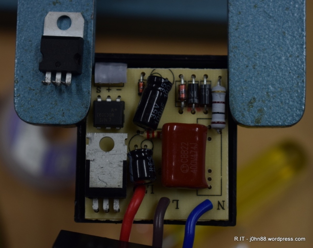
Here is a view of the top of the board, showing the bad triac on the board mounting.
In case you are wondering how small a 1206 resistor package is, it is 3.2mm long and 1.6mm wide, just don’t drop it on the carpet, since you may not find it again.
Oh, by the way, once assembled and wired up on the bench – it does work. The light would light up when I walked near it. Another successful Repair.IT
