Repair.IT or not – Dell Optiplex with no network connection

A month or two ago, my brother brought over to me, a Dell Optiplex machine. The complaint was that it couldn’t connect to the network. We had chatted briefly on WhatsApp about the problem – that his Dell has no internet, can’t locate lan connection, and can I bring it over tomorrow.

The Dell PC was dropped over, I wasn’t home, but my son was. When I got home, I set it on my test bench and connected everything up. Then had to contact him for the password, which I got in due course. Windows 11 was running on it, it logged on ok, but had a bit of an issue with the network, but after doing a few things, it was working – there was really nothing wrong, just that I had plugged the network cable into one of my lab networks, and my dhcp wasn’t turned on.

I don’t like to connect strange (as in not mine) machines to my home network, so have a number of different test networks that I can plug into. Anyway, the Dell was able to get an IP address. I ran the Windows Update which ran and downloaded a couple of months worth of updates and then put it aside. After a couple of days, powered it on and checked – yeap, still working. After doing a few checks I then packed it up.

What sort of checks do I do, you might ask? Generally the following:

  • Visual inspection of the network socket – check to see that all 8 pins are intact, i.e. not bent out of shape, or touching each other
  • Run Device Manager, check that the network device has a valid device driver – or update the device driver. Sometimes you see if with a yellow exclamation mark, which means there is a problem with it.
  • Check in Network and Internet settings, Ethernet – that IP assignment is Automatic (DHCP).
  • I look at error events in the System log, through the Event Viewer. It did show some errors about duplicate computer on the network – and was corrected by disabling netbios over tcp/ip.

Anyway, nothing else was untoward with the Dell PC, so my brother was informed – he said he would pick it up another day.

I don’t usually write about mundane things like this, but anyway, a week ago, he did come over to pick up the Dell PC. Then a few days later, he rang and said that it still wasn’t working.

I went through some standard troubleshooting. Was it connected direct to the router, or via a switch. He said it was through a gigabit router – D-Link. He sent me a picture of it.

I saw one orange light – and thought at the time, that was a bit strange. Actually I should have paid more attention. As he mentioned router, I thought that having one light lit was ok, so his Dell PC wasn’t connecting.

I then suggested setting a static IP address if he knows what the IP addresses should be like, and helped him to enter the right information – still no go. Next was asking if the router had been rebooted, he said that he had just done that – ok.

I suggested that if he had a USB Wireless Adapter, he could use that. Or if he has another laptop or something to plug into the same cable.

Anyway, he came back to me the next day saying that he fixed it. It turns out that he thought his laptop was working, but actually had been on Wi-Fi. He turned off Wi-Fi and connected to the network cable, and it didn’t work – just like the Dell didn’t work. So he went to check the cables from the NBN modem (which is actually the router), and eventually found that the cable from the router to the D-Link switch had come loose.

That was why I could see only one orange light in the photo. I should actually have had a closer look and seen that it was a D-Link DGS1005A 5-port switch and then asked about the cables at that time.

Anyway, the problem was solved, and I should have actually paid more attention to the information provided to me. Double check what is said – he said router, but the photo of the device had no antennas on it, and shows that it is in fact a switch – ok, live and learn, do better next time.

If I had gone through more of this troubleshooting, he might have been able to fix it without having to bring the Dell PC to me.

Repair.IT – 2CR Crystal locked FM radio

Six years ago, I wrote a post in which I had to recondition a slide switch in a crystal locked radio. It seems that the switch is playing up again, so it is time to do this again.

The 2CR crystal locked FM radio is a radio that has three channels, one of which is the 2CR station, and two others seem to be 2AC. These are relatively cheap radios, but I don’t like to throw them out if I can help it. The switch is a double pole triple throw (DP3T) slide switch, which I tried to find previously but gave up.

The radio was opened up and the switch was desoldered from the circuit board. Then removing the contacts, I can see that one part was again tarnished, and was not able to make any contact.

The large lower contact is the common connection, and this was causing the channel selection to fail. I had previously used sandpaper to clean the contacts, but this time I decided to use a sharpening block, like what we use for sharpening knives. I found that it takes less material off it.

It now looks different, doesn’t it? I then sprayed some contact cleaner on it and reassembled the switch. To confirm that the switch was working, I used a multimeter in resistance mode to check that the contacts were working in each switch position. So this repair will hopefully last another six years.

That wasn’t all! As usual, the radio has a telescopic antenna attached, and with usage and occasionally heavy handedness, the antenna broke – in the second section from the end.

The broken end is a bit sharp and can cause scratches. I thought about how I might repair it – or find a replacement antenna on ebay. Then I got a bright idea – I could make something to solder onto the end.

I had a brass screw that looked like a good size – so it was off to the lathe. I made some rough measurements, and it was only a matter of minutes before I was done – just in time for lunch. Since brass is quite a soft material, most of the time was taken up with measuring the diameter after doing a bit of turning.

There it is – the finished product still in the lathe chuck – can you see it? Maybe I should do some cleaning around the lathe so you can see it better?

Ok, there it is! The larger diameter is 2.8mm and the smaller diameter is around 2.43mm – maybe a bit larger, as I can try to see if it fits inside the broken antenna.

Here is the finished product with my rough drawing of how it would look. The fit is not too loose, as I will want to solder the two bits together.

After soldering – it looks quite nice, in my opinion. I left the screw head as it is, so as to show its origin. Then it was a matter of reattaching the antenna to the radio, solder the wire for it and back it goes together.

I left it playing and my wife came in and heard it – “Oh, you fixed it?”. That’s it for the time being. Take care and don’t go out too much, especially with our continuing Covid lockdown in place.

Replace.IT – Left and Right click switches on Logitech G700 Wireless Mouse

I was doing some cleanup in my house late last year and I came across a computer mouse that belonged to my son. It was a Logitech G700 Wireless Mouse that used a rechargeable NiMH battery. I asked him about it and he said that it was faulty – the left click would sometimes not click and/or would release even when pressed. He had replaced it with another mouse, so if I wanted to use it – I was welcome to it. As luck would have it, my Logitech wired mouse was also having some problems. Every so often, I would hear the beep tones that my mouse had disconnected on the USB and then would reconnect a moment later. It was strange as I could still see the mouse tracking led staying lit while this disconnect happened.

I tried the G700 mouse, and it had a really good feel. Yes, I could see that the left mouse button definitely had a problem. I looked on Google and could easily find people who had the exact same problem. As my son is an avid gamer, the left mouse button most likely had experienced a full life, such that the internal springs were weakened, which leads to this problem.

To open the mouse, I needed to remove the teflon glide pads to access the five tiny screws. It opens up easily and I could read the switch model numbers. I saw a D2FC-F-7N(10M) which was made by Omron. The 10M is probably the quality – 10 million operations. I checked on eBay and found a lot of people selling the D2FC-F-7N but no designator. Anyway, I wanted to replace both switches anyway, and the eBay pricing is such that the price for 10 is not much more than for 2, so I ordered 10 of them.

As expected, the delivery time from China is varied, and they arrived a week ago. I had a spare couple of hours this evening, so decided to get the job done. I opened the mouse again, and removed the mouse wheel, and then the metal bracket and plastic fittings that had held the mouse wheel in place.

As is my practice, I place the screws and bits and pieces in a sort of order, so that I can put these parts back together in the proper order.

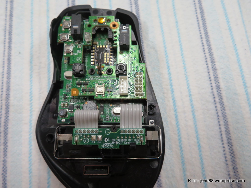
This top board needs to be removed – so that I can get to the switches – those black rectangular blocks with the white switch activator on the top. In order to do this, I will have to desolder 14 pins that can be seen at the bottom right of the top board. Let’s find out if my desoldering station is still working.

Yes, success – after some minutes, the top board was loose.

Here it is a closeup, then let’s see the bottom of the board.

Those large pads should be an easy job for my desoldering station.

Sure enough, the switches are off, and I now put the new switches nearby with the correct orientation, ready to go in.

Then soldering the switches were another easy job. Next step is to put the top board back on.

When the top board is in place, I will solder the 14 pins.

Ok – after an inspection through a magnifying glass, I think the job is done. Well, almost.

The mouse wheel supports are fitted now. You might see two tiny springs at the top, next to the black screws.

The mouse wheel is back in place. Now – where did I put the top cover?

There it is! I just need to connect that orange plug into the white socket, then close the cover, install the screws, and put the teflon glide pads back on – and the repair job will be completed.

The acid test – does it work? Plug the wireless mouse receiver into my laptop – put the battery back in, and switch the mouse on. Yes, it works – both buttons work as they should. Some of you might ask – if it was only the left mouse button that was failing, why replace both? The answer is that if one switch is failing, the other is not far behind. Another answer is that I have gone to the trouble of opening it up, so while I am there, I should replace the other switch at the same time. Agree? It is getting late, so bedtime for me – bye for now.

Replace.IT – Laser Switch on my Makita LS1017L Sliding Compound Saw – finally!

A couple of months ago, I mentioned how the laser switch on my Makita saw didn’t turn on the laser. I had pushed a piece of foam between the contacts, which made the switch work. Well, it did work – for quite some time, at least until yesterday afternoon – when I was trying to cut some of the final pieces of decking board.

My deck was completed, and what I was doing was to use the decking board to place on top of my raised garden bed to make it look nicer and also to have a place to sit when working on the veggies. Anyway, it was getting late, so I left it until this morning.

I needed to cut a couple of final pieces of board, and the laser would not come on – so I got out the replacement switch that I had purchased back then, and opened the switch cover. The foam had become compressed after all this time, so was not doing its job – therefore it was better to replace it finally. After removing the two wires that have spade terminals attached, it was an easy matter to use a small screwdriver and unclip the original switch. The new switch fit into place with a slight bit of force, and then the two wires attached, and screwed the cover back on.

The laser came on – great – and I quickly cut the boards, and now – I don’t have anything to use the saw for. Well, I will think of something – maybe a bench seat to fit onto the deck, yes – that sounds good, as I have a lot of ACQ treated pine left over from the garden beds – which is another story.

Repair.IT – Repeller Car Alarm Remote Control

Most recent cars have some sort of remote control, usually to allow central locking and or activate the inbuilt security, engine inhibitor, etc. Cars from more than 10 years ago, might have central locking, but a lot of them didn’t. We have always added an after-market security system, which in the Honda Civic was a Repeller Car Alarm, fitted by the car dealer. These car alarms and keyless entry system usually rely on a key fob remote control that disables the alarm and unlocks the doors. Generally there is a battery inside that needs replacing from time to time. Don’t you just hate it when you try swapping the battery and the key fob still doesn’t work? Usually that is the time to use the spare remote, but what do we do with the one that isn’t working? That is what I had to do, a few weeks ago, to use the spare remote – I didn’t have spare batteries, but at least the spare remote works.

Most of the time, the electronics in the remote control or key fob are very reliable. They have to be, as they are carried in pockets with all sorts of items such as keys and coins. Many times they are dropped on the pavement – how often have you fumbled with the car keys and dropped them in the night time?

So what could go wrong – usually it is the switch that is failing. The simplest way of checking this is to open the key fob or remote control. Generally it is held together by one or two screws, then the housing comes apart. A 12V battery is usually found inside, depending on the car – I know some manufacturers use coin batteries, which don’t last long but is easy to replace. If the battery contacts look a bit green, then the battery has been leaking and the contacts will need cleaning, otherwise they will be covered in an oxide that has a high resistance which can prevent the remote from working. On the small circuit board, there is likely to be at least one switch, quite often two or even three. I didn’t have spare switches as these are surface mount and quite small, 6mm x 3.5mm in size, and 2.5mm tall – I did find them on eBay so ordered some and waited for them to arrive.

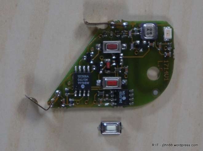
SONY DSC

The above photo shows the circuit board with the two switches, the red button is what is pressed when you press the rubber knob on the key fob. The white one is one of the replacement switches that arrived this morning. If you press the centre of each switch slowly, you should hear or feel a small click when the switch is activated. On my remote there are two switches, bottom one is to lock or unlock, and the top one is a panic switch – pressing the panic switch sets the alarm off, which is handy if someone is bothering you or trying to steal your car. I don’t think many remotes have this duress switch, but it can be handy at times. The lock/unlock switch doesn’t click which means it has more than likely failed.

If you have a multimeter, you can set it to measure resistance, then touch the probes onto each switch contact and press the switch – it is easy to say, but hard to do in practice. My switch is 6mm long, so after putting the probes on the switch, I need to use a small screwdriver to press the switch button. In my case, the resistance drops briefly but does not stay low, which confirms that the switch has failed. I can get it to stay low by pressing quite hard, but if I relax a little, it goes back high resistance. Ok, so to replace the switch.

I could use my hot air rework station to remove this switch, but I happen to already have a smd rework iron, which has tweezer tips. It is a simple matter of waiting a minute for the iron to heat up, then using the iron, clamp on both switch contacts, wait a few seconds, then lift the switch off the circuit board. Heating the contacts is fine, but when clamping on the switch, it does melt the switch plastic a little. To solder the replacement switch back on, we can do the same – but it is easier to use a conventional soldering iron since I need to hold the switch in place, solder one contact first, then solder the other end.
The replacement switch cost a princely sum of $2 for a packet of 20 – good price. I could have bought one if I could find a local supplier, but it would have cost a few dollars, so now I have 19 spares. Anyone need a switch?

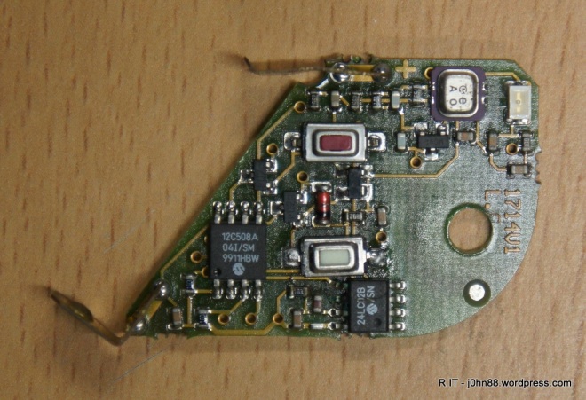
SONY DSC

The photo shows it soldered in – yes, I know it is at a slight angle, but it should be fine. I tested it and it is working better than the original switch. However, during testing, the battery started to die. It did unlock and disable the alarm, but I could not get it to lock, unless I waited a few minutes for the battery to recover some charge. But at least the switch replacement is working, so now, I can order a couple of spare batteries – or maybe 5 because 5 costs less than buying 2 – how does that work?

Recondition.IT – Slide switch for crystal locked FM Radio

We have one of those three-channel crystal-locked FM Radio – commonly used for listening to the China Radio station 2CR and others.  It had been playing up at times and was unable to tune into any channel and was put aside a while ago.

It is a DP3T slide switch that is the problem.  Dual Pole 3 Position slide switch – with pin spacing at 2.5mm apart.  I was looking for alternatives and could find switches that have pins 2mm and 3mm apart, but not 2.5mm.  After some time, I was able to find a similar switch – a SK-23E01G, but would you know, I cannot find anyone who has stock of this switch.  I did find a couple of sites that do advertise this switch, but they require pre-ordering and have a minimum quantity of 1000 units – fantastic, except that I only need one piece.

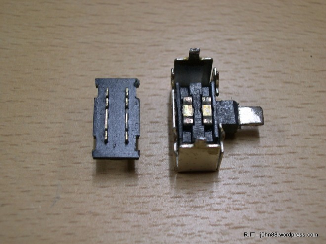
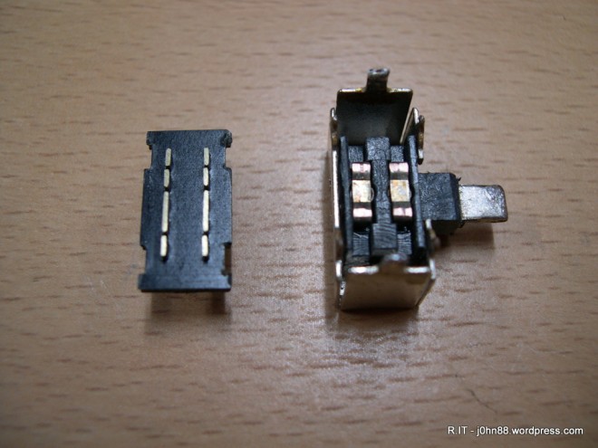
My only option is to buy a new radio, or to “recondition.IT” – the switch that is.  The switch is used to select from one of three crystals that determine the frequency that the radio is tuned to.  I removed the switch from the pcb, then opened the housing.  It was immediately obvious that the switch contacts were worn and were oxidised.

DSCN5032

There are two movable contacts – but the fixed contacts are not allowing good contact. To fix this, I used a 240 grit emery paper, to polish up the contacts, followed by 320 grit paper.

DSCN5033

Now this looks better – at least the contact surfaces are shiny.  I reassembled the switch, then checked the switching resistance, and it was good.  Great, installed the switch, closed the radio, added four AA batteries, and voila – it was working.  Not bad for about 10 minutes work.