Occasionally, in the electronic repair world – we may be unable to obtain replacement parts. In a situation like this, we then have to resort to replacing the module that has failed, either with modules from the manufacturer or modules that have a similar function.
This is about my Wise 2086 Professional Electronic Tension Head – which is mounted on my Spinfire Flame Stringing Machine. The tension head allows the string to be gripped, then pulled linearly until the required tension is reached – then, if constant pull is enabled, it will continue to keep that tension. A couple of weeks ago, I noticed that one of the segments on the second LED display didn’t light up. For those who know about 7 segment LED displays, it was the B segment. Sometimes like today, on powerup – it will be working.
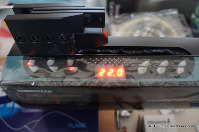
Wise 2086 Tension Head – display working
But then later on, the B segment will stop.
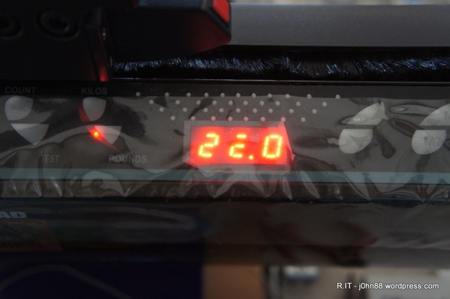
Wise 2086 Tension Head – display not working properly
A couple of weeks ago, I emailed an enquiry to the supplier in Melbourne, Tennis Warehouse – from where I purchased this stringing machine about three years ago. I asked about any problems if I open up the tension head and mentioned the display problem. I had heard on the internet that occasionally, opening up the tension head would give an error on next powerup, that would require some procedure to be followed. I received a quick response that this will not happen, and that the screws are different lengths – something to watch out for when I open the case. Also that the display board is available for $45.
Just a week ago, on Friday, once I had finished stringing a few racquets – I opened up the case, then had to remove the main carriage to get to the display board. I removed the board and checked the part number of the LED display. It was a HS-3101AS – which is a 0.3 inch display but in a larger housing with 10 pins. I checked my usual supplier – element14, to no avail – this part didn’t appear to be available and I was unable to find an equivalent. A search on the internet also gave me a possible equivalent – HS-3101AX, but this also didn’t help.
I could find other similar size displays but when I check the pin connections, those are in two columns of five pins, 5 mm between columns, but mine are 7.62mm between columns. I could find it on alibaba, except that they only indicate it as being an integrated circuit will no actual photograph – so I was hesitant at ordering something, sight unseen. I decided then, to bite the bullet and order a replacement display board. I had to email a photo of the display board so that they could confirm the correct replacement. Then on Thursday – my replacement board arrived.
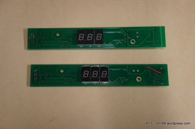
Display board for Wise 2086
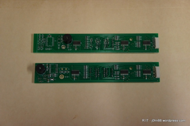
Display board for Wise 2086
The top on is the original, version 3.1 and the replacement is at the bottom – version 3.3. Some slight differences – the main thing being that the speaker was moved, making it much easier to install the board.
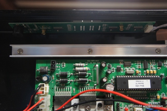
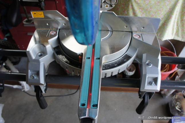
Wise 2086 Tension Head
Here is a photo of the board installed – at the top. Previously the speaker would get in the way of my fingers when trying to remove and install the small brass nut.
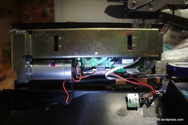
Wise 2086 Tension Head
Then a photo with the carriage mounted back on.
Next thing to do is to work on one of the base clamps on the stringing machine – which had been causing problems that it would unlock, when I didn’t want it to. Tennis Warehouse sent me a replacement base clamp at the same time as the display board which was very good of them.
The motto of the story is that you cannot always replace component parts – in fact, not many companies will do this, even for manufacturers – they usually replace the module. Sometimes, if the modules are valuable – they are returned to the factory for refurbishment – which usually means replacing the faulty components, but not always. The common factory refurbished cameras and whitegoods – are usually just repaired with replacement modules – often happens with goods that are dead on arrival, they go back – repaired by swapping modules, then comes back out as factory refurbished at a very good price and with warranty, generally.