Repair.IT – Benq GL2250 LED Monitor, Part 2

Well I should have known that perhaps it wouldn’t be that simple.

I reassembled the monitor last night and this morning connected it to my laptop for testing.  It powered up perfectly and appeared to be working fine.  I left it and came back after a while – the displays were off, due to power saving settings, pressed a key on the keyboard and…

IMG_2752

Ok, so the problem wasn’t fixed – looks like two sections on the bottom right were not lighting up.  Power off and back on, then it was fine again.  The MP3394 drives 4 LED lines – the IC had been replaced, so it is very unlikely to be faulty – therefore, the fault must not lie in the MP3394 – ok, that is now settled.

IMG_2753

After some time, I woke up the monitor again – this time, the bottom left was also out, in additional to the bottom right hand two.  If a LED line was out, then the entire section should be out, not one of two – so it looks like possibly, that the LED backlights are at fault.

One thing that doesn’t make sense is that if the LED’s were overheating and then failing, the fault should be permanent, but it seems to get better after a power off and on, but not always it looks like.  I also don’t know how the LED strings are attached to the LCD panel.  I am expecting that they would be in a row, so likely two strings for the top, two strings for the bottom.

So for now, the repair hasn’t been successful, but that is the name of the game.  I will test the others until I end up with a panel where the LED backlight is off permanently – then can take the panel apart to see if the LED itself has failed.  I might also check the input voltage to the MP3394 to see if that is acting up.  Let’s leave it at that, and I will update with a Part 3 if I make any further progress.

P.S. Why am I writing these articles so quickly – I picked up another 6 month contract job, part-time that starts next week.  Life happens, lol.

Repair.IT – Generic brand CD Boombox

Back in March, a neighbour brought over a CD Boombox – that was its name.  No brand names visible – so it is one of the generic products that are manufactured in China.  It would play CD’s or cassette and had AM/FM radio as well.  It came with a plug in power cord, and it also had provision for having 8 D cell batteries.

The problem was that it would not turn on.  I verified that if I supplied 12V from a small lead-acid battery that I could get it to turn on and play a CD, so it looks like the internal non-power sections are working.  In due course I opened it up, removing about 8 screws then the case opened up, revealing a lot of cables to be disconnected before the two halves come apart completely.

IMG_2678

The photo shows the insides of the boombox, upside down.  The CD mechanism is seen at the lower middle of the picture with the cassette mechanism at the upper middle.  Four speakers were visible as you can see.  After some checking, I noted that one of the diodes – those black bits on the lower left of the printed circuit board, was shorted – which could well cause the problem.

IMG_2692

I removed the failed diode – a 1N5393, which I didn’t have a good replacement for so found a supplier on eBay and ordered some.  It arrived after a couple of weeks, then I soldered it in and tried it out, still no go.  Ok, so what else is the problem?

One the other half of the case, there is a transformer, and from the secondary windings,  a cable plugs into the board.  I connected the power cord, then measured the output of the transformer – nothing.  I then measured the input to the transformer, i.e. the power cord, and got no resistance.  After some further investigation, it appears that this transformer has an integrated thermal fuse and that this fuse has failed.  I cannot get to the fuse without disassembling the transformer, and I could not get replacements of this transformer either.

In order to not have this sitting around for a long time, I found one of those adjustable power packs – a Dick Smith one that had a switch for choosing the voltage.  It had been sitting around in my spares box for years, so decided to repurpose it.  I drilled a small hole in the case and fed the cable from the power pack through, then connected it to the battery box terminals through a diode to protect it if batteries were inserted.

Then powering up, it played CD’s – great.  Just a matter of putting the Boombox together and get it back to its owner.  Since the cost of parts was quite minimal – the two diodes ended up costing 40 cents and the power pack had been around for probably 30 years – it was just another charity repair job.  To now, I understand that it is still performing well.

Resolder.IT – DC-DC Converter from eBay

While I had the soldering iron out for the Benq GL2250 monitor power supply repair, I thought I should fix up this pending job.

I had bought some DC-DC converters from eBay in the past.  Some were buck converters which meant that the output voltage could higher than the input voltage.  Others were standard down converters so will produce a lower voltage.  This can be ideal if you want to power 5V devices like a Raspberry Pi from a car battery at 12V.

IMG_2751

One of those that I had bought had a three digit meter that could display the input or the output voltage measurement depending on which button was pressed.  I had ordered two of them, and when they arrived, I noticed that something wasn’t right about one of them.  Sure enough when I opened the sealed packet, the converter came out and a loose capacitor as well.  I contacted the vendor, and they were kind enough to come to an arrangement with me.

Anyway, this had been put aside since I only needed to use one of them.  But since the soldering iron was out, I thought – why not resolder the capacitor.  The capacitor is a surface mount type, and it looked like it had not be flow soldered properly.  I used the soldering iron tip to wipe both contacts, so that it flowed the solder on the pads.  Then put a drop of flux on each pad, set the capacitor in place – then while holding it down, I touched one pin with the soldering iron tip that was wetted with solder.

Then turn around the board, and do the same with the other pin.  Of course making sure that the capacitor was oriented the correct way.  After using the 9x magnifier again to visually check it, I decided to wet each pin with the soldering iron again, just to make sure.

Anyway, I was happy with the results and I can put this DC-DC converter away until I need it for some project.  Another quick repair – that had been sitting around for a while.

P.S. The black bar or stripe on the capacitor designates the negative electrode.

Repair.IT – Benq GL2250 LED Monitor, Part 1

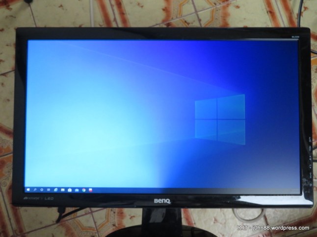
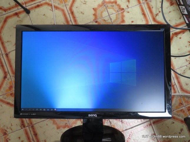
Sometimes for some reason or other, repair jobs may sit around for a while – here is one of those.  I had been given a number of these monitors by my brother.  They had been found thrown out in a loading dock in the city, probably from an office cleanup.  The Benq GL2250 is a full HD monitor that is LED backlit and when I had the time to test them – I found that the reason these had been disposed of, was that part of the screen would go dim.  It appeared to be part of the LED backlight that was going out, and turning the monitor off and on again, would often restore operation for a time.

Since a 22″ monitor is still a reasonable size to use in the home office, and there were several of these with the same problem – I thought it would be good to repair them and get them working consistently.  Certainly it would be worth a blog article.  After disassembly, I was able to get to the power supply board, and on that board I found a MP3394 4-string White Led Driver integrated circuit.

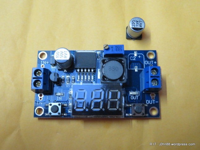
I could access the cable from the power supply to the LED backlight – so decided to do some measurements, in the sense of leaving a voltmeter connected to one of the lines – to see what happened when parts of the screen dimmed out.  After some of these measurements – which took time, due to the intermittent nature of the fault – I concluded that either the driver was at fault or maybe a faulty LED in the backlight.

Replacing the led in a backlight is not a simple operation, so I elected to try replacing the driver IC.  On eBay, I found a vendor selling 5 pieces of these MP3394 devices for US$6.99 + US$1.00 for delivery – a reasonable price, so I ordered them.  In time, the parts arrived and I put the parts together with the first printed page of the MP3394 datasheet.  Then life happened – as it does.  Just like that?  Well, the reason was that a couple of weeks earlier, I was asked to go in for an interview for a challenging job, and was offered a full-time contract job that was for 6 months, but actually turned out to be nearly 3 years.

I could have come back to this repair job, couldn’t I?  The new job was interesting, challenging and much of my time was spent working, so after getting home – I was tired, and didn’t feel like doing anything other than relaxing.

It isn’t really an excuse, but when I say life happens – it certainly does.  I went on to do some studying in Cyber Security which I had been planning to do for over 10 years.  This time I committed to do the training, CompTIA Security+, then CompTIA Cyber Security Analyst+ (CySA+), and only a couple of weeks ago, I completed CompTIA PenTest+.  By completing, I mean studying for and passing the exams.

I also studied CCNA CyberSecurity Operations at TAFE, and since I did well in the final exam, I received a discount voucher for the actual Cisco exams.  I then eventually sat for and passed both Cisco exams achieving the Cisco Certified CyberOps Associate certification.  But I digress – I really wanted to talk about the repair of this BenQ monitor, but now you understand by what I mean that life happens.

IMG_2749

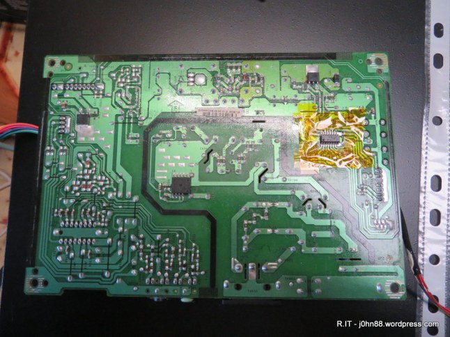
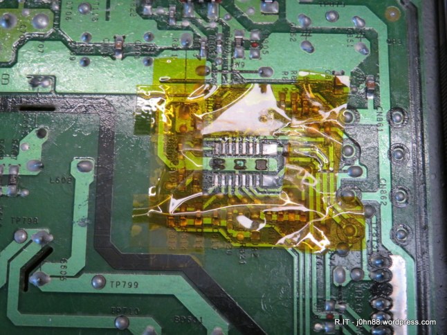
The MP3394 is a chip in a 16pin SOIC package.  It is a surface mount chip, so I masked out the area around the chip with heat resistant tape – to protect the other parts nearby.  After brushing some flux onto the pins, I applied the hot air gun onto the chip, and moved it around and around to get the chip and pins hot enough that it would then come off.

Actually it took a few minutes – I had the hot air gun set to 300 Celsius and airflow around 80%, which might have been too high – but it worked.  After a bit of time, I could see and feel that the solder was molten, but the chip would not come off – and after another minute – it then came off.  I was grabbing the chip with curved tweezers.  When the chip was off, I found that there was three spots of glue under the chip, which is often used to keep the chip in place during flow soldering.

IMG_2748

Then a quick cleanup using soldering wick, flux and the soldering iron to remove the left over solder, and leave a clean flat surface on all of the solder pads.  Next step is to get the new chip in place, tack a couple of corners with solder to keep it in place, then solder each side of the chip.  Soldering each side is done by putting more solder on the soldering iron tip, then wiping the tip down each row while holding the iron at an angle, so that the pins and pads are heated together and the flux allows the solder to flow and make a good join.  With practice, you can get very good results.

I had a problem in that one of the pins on the IC was bent up, and I didn’t notice it when I was placing the IC – so good idea to double check before soldering.  Since it was a single pin, I just pressed down with the soldering iron tip until it made contact with the pad.  Then I visually inspected each joint with a 9x magnifier.  To verify, I used a multimeter in the resistance measuring mode, and checked each pin was connecting to the solder pad test points, which were conveniently placed near each pin.

Next step will be to reassemble the monitor and check that the backlight fault is resolved, but the results of that will be in Part 2.  To be continued…